
When you plug an electric vehicle into a fast charger, the power electronics inside that station are working hard. They are converting AC from the grid into DC that goes into your car battery, and this process generates serious heat. For EV charging station manufacturers, keeping those electronics cool is not optional. It is the difference between a reliable 150 kW station and one that shuts down thermally after ten minutes of operation. That is why more engineers are turning to metal core PCBs, also known as MCPCBs, as their go-to solution for Thermal Management in these demanding applications.
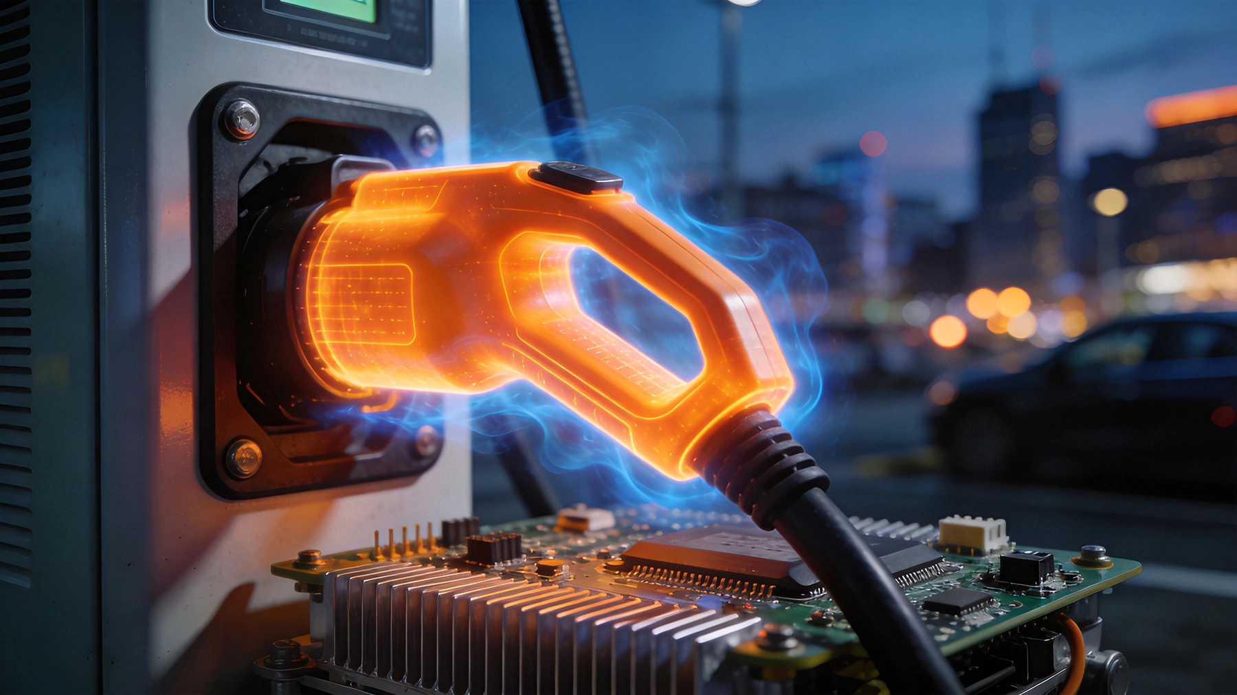
Electric vehicle charging stations, especially those operating at high power levels above 50 kW, pack a tremendous amount of power electronics into a relatively compact enclosure. The key components inside include:
Each of these stages involves semiconductor devices, typically silicon carbide (SiC) MOSFETs or insulated gate bipolar transistors (IGBTs), that switch at high frequencies. When you combine high voltage, high current, and high switching speeds in a small space, heat accumulates fast. A modern 350 kW ultra-fast charger can waste 5 to 10% of input power as heat. For a station delivering 350 kW, that is 35 kW of heat that has to go somewhere. Without effective Thermal Management, junction temperatures climb, semiconductor lifetime drops dramatically, and reliability suffers.
Traditional FR4 circuit boards are poor thermal conductors. The standard epoxy laminate used in conventional PCBs has a thermal conductivity of roughly 0.3 W/mK. Compare that to aluminum, which sits around 205 W/mK, and you can see why metal core PCBs change the game. An Mcpcb replaces the standard FR4 dielectric with a thin, thermally conductive dielectric layer, usually between 75 and 150 microns thick, that sits directly on a metal base, most commonly aluminum.
The metal base acts as a heat spreader. Heat generated by components on the board surface flows through the dielectric and into the metal substrate. From there, it can be conducted to a heatsink, fan, or liquid cooling plate. The result is junction temperatures that are 20 to 40 degrees Celsius lower than the same layout on standard FR4, depending on power density and layout.
The fundamental advantage is heat spreading. The aluminum or copper base in an Mcpcb provides a low-resistance thermal path that carries heat away from hotspots under power semiconductors. This matters especially for switches like SiC MOSFETs, which perform best below 150 degrees Celsius junction temperature. Getting the heat out efficiently lets these devices run closer to their performance limits while staying within safe operating windows.
Because thermal resistance is lower, engineers can pack more power into the same footprint. This is critical for fast chargers, where station designers want maximum power delivery from a unit that still fits in a urban charging hub or parking garage. MCPCBs allow tighter component spacing without thermal crosstalk between adjacent devices.
Charging stations are outdoor infrastructure. They see temperature swings from freezing winter mornings to sweltering summer afternoons. The metal core in an MCPCB also provides a good coefficient of thermal expansion (CTE) match between the board and attached heatsinks, reducing mechanical stress on solder joints over thermal cycles. This translates to fewer field failures and lower maintenance costs over a station lifetime that can exceed ten years.
Power stages in EV chargers require thick copper traces to carry tens or hundreds of amps. Metal core PCBs support heavy copper constructions, typically 2 oz to 6 oz per square foot, and some manufacturers can go even heavier. Combined with the thermal benefits of the metal substrate, these heavy copper traces can carry high currents without excessive temperature rise.
Not every circuit inside an EV charging station needs a metal core. Control logic, communication interfaces, and low-power sensing circuits run fine on standard FR4. The metal core is reserved for the power stage, and here is where you typically find it:
Not all dielectric layers are equal. Standard MCPCB dielectrics are thermally conductive epoxies filled with ceramic particles. Common options range from 1 to 5 W/mK thermal conductivity. For EV charging applications with significant power density, a dielectric rated at 2 to 3 W/mK is the practical minimum, with premium materials going higher for the most demanding designs.
The dielectric thickness also matters. Thinner dielectrics give better thermal conductivity but reduce electrical isolation between the circuit and the metal base. Engineers must balance thermal performance against safety isolation requirements, typically defined by industry standards like UL 60950 or UL 62477 for power electronics.
The MCPCB does not cool itself. The metal base typically mounts to a heatsink or cooling plate, and the interface between the board and the heatsink is a critical thermal joint. Using quality thermal interface material (TIM), whether thermal paste, thermal pads, or phase change materials, makes a measurable difference. A poorly applied TIM can add 0.5 to 1.0 degrees Celsius per watt of thermal resistance, which at 1,000 watts of dissipated heat adds 500 to 1,000 degrees Celsius of temperature rise. Nobody wants that.
Heavy copper traces on MCPCBs need careful layout. Wide traces reduce current density and lower resistive heating. When routing high current paths, keep trace lengths short, use fill areas generously, and avoid sharp corners where current crowding occurs. For the highest current paths, consider using separate bus bars or heavy copper assemblies that bolt directly to the MCPCB, distributing current away from the board itself.
Put your hottest components directly over the metal base, not near board edges or over unsupported spans. Thermal vias under QFN, DPAK, or TO-247 packages help conduct heat through to the metal core. Avoid placing thermal hotspots near temperature-sensitive components like electrolytic capacitors, which have lower temperature ratings and degrade faster when exposed to sustained heat.
The two main metal core options are aluminum and copper. Aluminum is lighter, cheaper, and sufficient for most EV charging applications where power levels stay below roughly 50 kW per module. Copper base offers about twice the thermal conductivity of aluminum, making it the right choice for ultra-high-power designs above 100 kW per module or where heat flux is extremely concentrated.
From a manufacturing standpoint, aluminum MCPCBs are more established, with broader supplier base and lower tooling costs. Copper cores require more specialized processing because copper is harder to machine and has different thermal expansion characteristics. For most station manufacturers, starting with aluminum and moving to copper only when thermal requirements genuinely demand it is the practical path.
In one documented case from a 60 kW fast charger redesign, switching from a FR4-based power module to an aluminum MCPCB with 2 W/mK dielectric dropped the maximum junction temperature of the SiC MOSFETs from 142 degrees Celsius to 108 degrees Celsius under full load. The charger could now sustain continuous output at 40 degrees Celsius ambient without thermal throttling, compared to the original design that would throttle after 20 minutes at the same ambient temperature.
The MCPCB also allowed a 15% reduction in the size of the heatsink, because the board itself was doing more of the thermal spreading work. Overall system size decreased, and the manufacturer reported a 30% improvement in mean time between failures (MTBF) in field deployments over an 18-month observation period.
Silicon carbide and gallium nitride semiconductors are replacing traditional silicon IGBTs in modern EV chargers because they switch faster and lose less energy as heat. Sounds counterintuitive, but faster switching actually creates more concentrated heat in certain respects because the dv/dt and di/dt slopes are steeper. This means thermal management challenges do not go away with wide bandgap semiconductors. If anything, the need for excellent thermal paths to the board and heatsink becomes more critical.
MCPCB manufacturers are responding by developing higher-performance dielectrics with thermal conductivities above 8 W/mK, as well as hybrid constructions that combine metal core with direct bonded copper (DBC) substrates for the most demanding semiconductor packages. Expect to see these advanced thermal management solutions become standard in the next generation of ultra-fast chargers rated above 400 kW.
Metal core PCBs are not a luxury in EV charging stations. They are a practical engineering solution to a real thermal problem. By providing a low-resistance thermal path from hot components to the heatsink, MCPCBs enable higher power density, better reliability, and smaller enclosures. For engineers designing charging infrastructure or for manufacturers selecting components, understanding where and how to apply MCPCB technology is becoming an essential skill as the EV market continues its rapid growth.
The key is matching the right metal core construction to the actual thermal load, choosing dielectric materials that balance conductivity and isolation, and integrating the board properly into the broader thermal management system including heatsinks, fans, and thermal interface materials. Get those details right, and the charging station will keep delivering power reliably through years of daily use.
Yes. MCPCBs handle outdoor temperature extremes well because the metal base provides good thermal cycling performance and mechanical stability. The key is ensuring the overall enclosure and thermal interface design accounts for the full operating temperature range, typically -40 to +60 degrees Celsius for public charging infrastructure.
Metal core PCBs typically cost 2 to 4 times more than equivalent FR4 boards due to the metal substrate, specialized dielectric materials, and different Manufacturing Process. However, when you factor in reduced heatsink size, improved reliability, and smaller overall system footprint, the total system cost often comes out neutral or even favorable, especially in high-volume production.
For a power module in a 50 kW charger, a dielectric thermal conductivity of at least 2 W/mK is recommended. Many designers target 3 W/mK for a safety margin. The exact requirement depends on power density, semiconductor choice, and allowable junction temperature, so thermal simulation is advisable for critical designs.
Yes, with minor adjustments. Standard SMT reflow profiles work, but peak temperatures may need to be slightly higher because the aluminum base acts as a heat sink during reflow. Lead-free solders with higher melting points are commonly used. Most contract manufacturers with experience in power electronics can handle MCPCB assembly without special equipment.
Alternatives include DBC (direct bonded copper) substrates, which offer very high thermal conductivity but at higher cost and with more limited circuit complexity. Liquid cooled bus bars and embedded cooling channels in the enclosure are also used in ultra-high-power chargers. MCPCBs remain the most cost-effective general solution for most power levels from 10 kW to 150 kW.

Finding the Right China Flexible PCB Manufacturer for Wearable TechJune/12/2026

Top 10 DFM Tips to Avoid Errors in Your Next PCB OrderJune/18/2026
Why is My High-Speed PCB Experiencing Signal Reflection?September/07/2026
ADAS Systems and the Need for High-Speed, High-Frequency PCBsSeptember/20/2026

How We Handle Intellectual Property Protection for Overseas ClientsOctober/19/2026
Thru-Hole vs. SMT: Choosing the Right Assembly TechnologyJuly/28/2026
Flexible PCBs in Modern Cars: Sensors, Displays, and Comfort SystemsSeptember/01/2026
Introduction to Flexible Printed Circuit Boards (FPC): Beginner's GuideMay/18/2026