Open Nav

If you've ever wondered how foldable smartphones maintain electronic connections across hinge mechanisms, or how medical devices fit complex electronics into constrained spaces while needing mechanical support, the answer lies in rigid-Flex Pcb Technology. As a China Rigid-flex Pcb manufacturer with 12+ years of experience producing millions of these specialized boards annually, we're sharing our comprehensive knowledge to help you understand this powerful technology.
Rigid-flex PCBs combine the best of both worlds: the mechanical stability and component mounting capability of rigid boards, plus the flexibility of Flex Circuits enabling bending and folding. This hybrid construction has become essential for products requiring both high component density and mechanical flexibility.
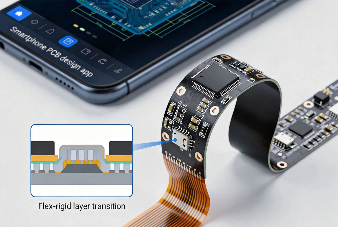
A Rigid-flex Pcb is a hybrid circuit assembly permanently integrating both Rigid Pcb sections and Flexible Circuit sections into a single, unified board. Unlike assemblies where rigid and flex boards are connected via connectors or cables, rigid-flex boards have Flexible Circuit sections laminated directly to rigid board sections, creating a seamless electrical and mechanical connection.
The technology was first developed for military aerospace applications in the 1980s but has since become mainstream in consumer electronics, medical devices, automotive systems, and industrial equipment. China has emerged as the global leader in rigid-flex production, accounting for over 55% of worldwide output.
Core characteristics of rigid-flex PCBs:
Typical rigid-flex construction:
A typical 8-layer rigid-flex board might consist of:- 4-layer rigid section with high-density component mounting- 4-layer flexible section with Controlled Impedance signal routing- Seamless transition zones where rigid and flex layers are bonded together- Component mounting possible on both rigid and flexible sections (with appropriate stiffeners)
Rigid-flex PCBs combine multiple structural layers to achieve their unique capabilities:
The rigid sections of a rigid-Flex Pcb use standard PCB construction:
The flexible sections use FPC construction:
The areas where rigid and flex sections meet are critical to rigid-flex performance. These transition zones involve:
Rigid-flex technology offers compelling benefits over traditional approaches using separate rigid and flex boards:
Eliminating connectors and cables between rigid and flex sections removes potential failure points. Where traditional assemblies might have dozens of connector pairs (each a potential failure point), rigid-flex boards have seamless electrical connections. This reliability improvement is especially critical for aerospace, medical, and automotive applications where failures can have serious consequences.
In our experience, rigid-flex boards typically achieve 2-3x higher mean time between failures compared to equivalent rigid-plus-cable assemblies, representing a significant reliability improvement.
Rigid-flex boards eliminate the need for connector housings, cable lengths, and additional mounting hardware, saving substantial space and weight. Typical space savings range from 30-50% compared to separate rigid and flex board assemblies with equivalent functionality.
For space-constrained applications like foldable smartphones, this size reduction is the difference between a practical product and one that's too bulky for the market. For aerospace applications, weight reduction directly translates to lower launch costs and improved payload capacity.
Rigid-flex boards arrive as complete assemblies, eliminating the need to connect separate rigid and flex boards during assembly. This reduces:
Rigid-flex boards enable superior electrical performance compared to separate board assemblies:
Rigid-flex technology enables product designs impossible with conventional approaches:
Rigid-flex PCBs are used across diverse industries requiring both complexity and flexibility:
Foldable smartphones and tablets represent the largest consumer electronics application for rigid-flex technology. These devices require high-density component mounting on rigid sections for processors, memory, and cameras, while flexible sections in hinge areas must survive hundreds of thousands of fold cycles.
We produce rigid-flex assemblies for major smartphone brands, delivering boards with reliability exceeding 500,000 fold cycles—essential for consumer products with 3+ year expected lifetimes.
Other consumer applications include:
Medical applications demand the highest reliability and Miniaturization:
Modern vehicles increasingly use rigid-flex technology:
Aerospace applications demand weight reduction and reliability:
Rigid-flex manufacturing combines processes from both Rigid Pcb and FPC production, with additional complexity at the transition zones:
Proper design is critical for rigid-flex reliability. Based on our production experience:
Key guidelines:
Follow minimum Bend Radius rules:
Route traces perpendicular to bend axis to minimize stress on copper conductors. Use rolled annealed copper for dynamic flex applications requiring millions of bend cycles.
Layer assignment recommendations:
Rigid-flex boards typically cost 2-4x more per unit area than equivalent rigid PCBs, but often reduce total system cost by eliminating connectors, cables, assembly time, and field failures. For applications requiring both flexibility and component mounting, the Total Cost Of Ownership analysis frequently shows rigid-flex as the most cost-effective solution despite higher per-unit board cost.
Repairing rigid-flex boards is generally difficult and not recommended, especially for high-reliability applications. Small trace repairs are sometimes possible for prototypes using conductive epoxy or micro-soldering techniques, but these repairs reduce reliability and are only suitable for low-volume situations. For production designs, replacing damaged boards is almost always more cost-effective than attempting repair.
Most rigid-flex boards use 4-8 layers total, with 2-4 rigid layers and 2-4 flex layers. Complex applications like aerospace systems and medical imaging equipment may use 10-20+ layers, with multiple rigid sections connected by flexible sections. The exact configuration depends on your specific circuit density, mechanical requirements, and electrical performance needs.
Yes, rigid-flex boards are widely used for high-frequency and high-speed applications. The flexible sections can be designed with controlled impedance characteristics using appropriate material selection (such as LCP for very high frequencies) and precise trace geometries. For 5G mmWave, high-speed computing, and RF applications, rigid-flex technology is often preferred over traditional approaches.
Essential testing includes: 100% electrical testing for continuity and isolation, visual inspection under magnification, bend cycle testing for dynamic flex applications, adhesion testing for transition zones, impedance testing for controlled impedance designs, and Environmental Testing (thermal cycling, humidity exposure) for harsh environment applications. High-reliability applications like medical and aerospace should also undergo accelerated life testing.
Rigid-Flex Pcb Technology enables product designs impossible with conventional approaches. From foldable smartphones to medical implants, aerospace systems to industrial equipment, rigid-flex boards deliver the mechanical flexibility, electrical performance, and reliability modern products demand.
As an experienced China rigid-Flex Pcb manufacturer, we've supported clients across diverse industries in bringing innovative products to market. Our engineering team provides free Dfm reviews, design consultation, and Rapid Prototyping to help you successfully implement rigid-flex technology.
Ready to leverage rigid-flex technology for your next project? Upload your design files today for a free Dfm review and quotation. Our engineering team will provide detailed feedback on manufacturability, cost optimization, and reliability considerations specific to your application—helping you bring innovative products to market with confidence.
Sustainability in PCB Fabrication: Eco-Friendly Materials and ProcessesJuly/01/2026
Blind and Buried Vias: Enhancing Density in HDI PCBsSeptember/30/2026
How to Prevent Common Failures in Flexible Circuit DesignSeptember/09/2026

Detailed Explanation of the Types, Materials, and Applications of Flexible Circuit Boards 101June/04/2026
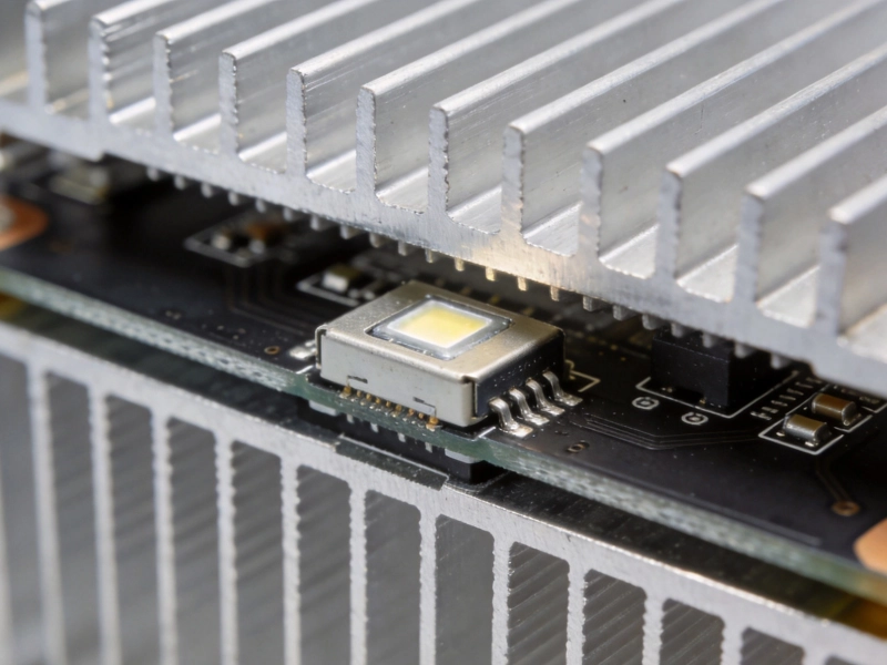
Metal Core PCB (MCPCB) Basics: Aluminum vs. Copper SubstratesSeptember/29/2026
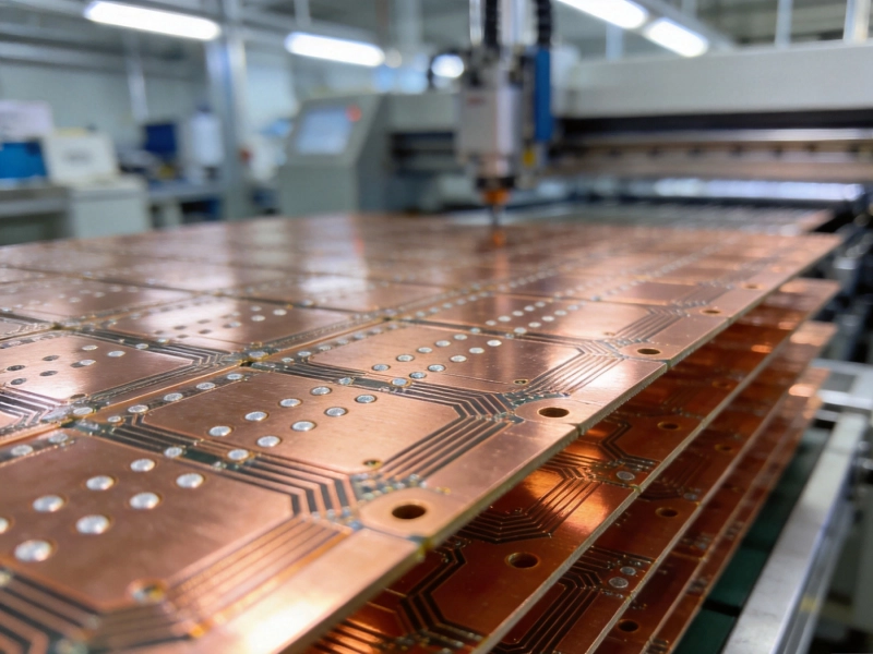
How DFM Analysis Saves You Money on Multilayer PCBsAugust/19/2026
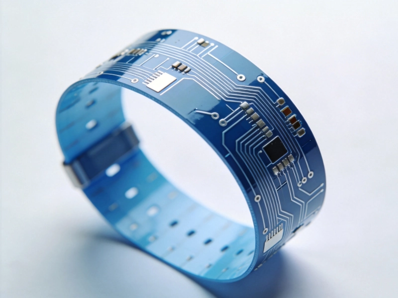
Wearable Health Monitors: The Importance of Biocompatible Flex PCBsSeptember/02/2026
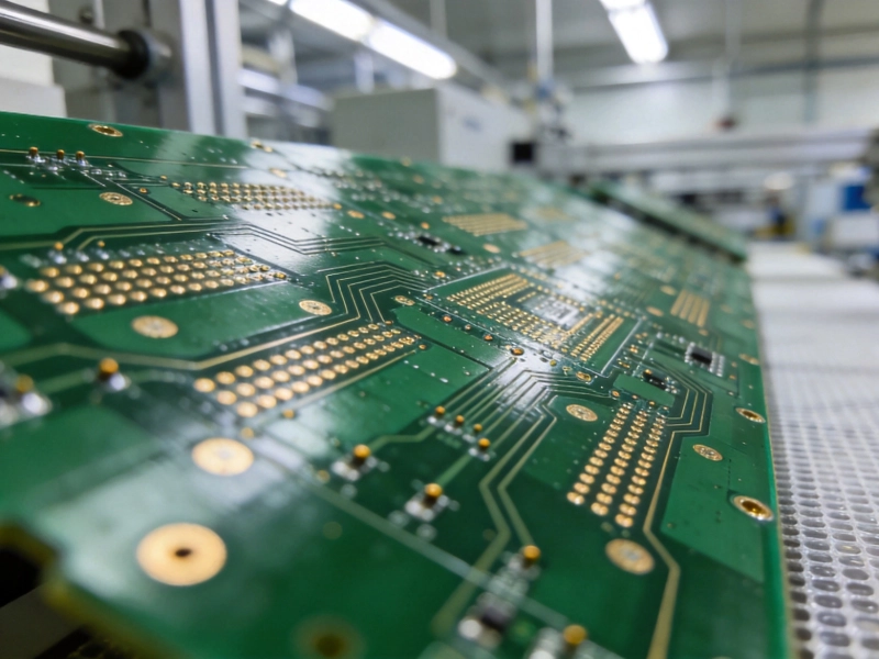
The Hidden Costs of Cheap PCBs: Why Quality MattersJuly/23/2026