Open Nav

If you've ever wondered how foldable phones bend without breaking, or how fitness trackers conform to your wrist while packing complex circuitry, the answer lies in flexible Pcb Technology. Flex PCBs have revolutionized Electronics Design by eliminating the constraints of traditional rigid circuit boards, enabling entirely new product form factors previously thought impossible.
As a leading China Flex Pcb manufacturer with over 12 years of production experience serving clients across 30+ countries, we've seen flex technology transform entire industries from consumer electronics to medical devices. In this comprehensive guide, we'll break down everything you need to know about Flexible Printed Circuit Boards.
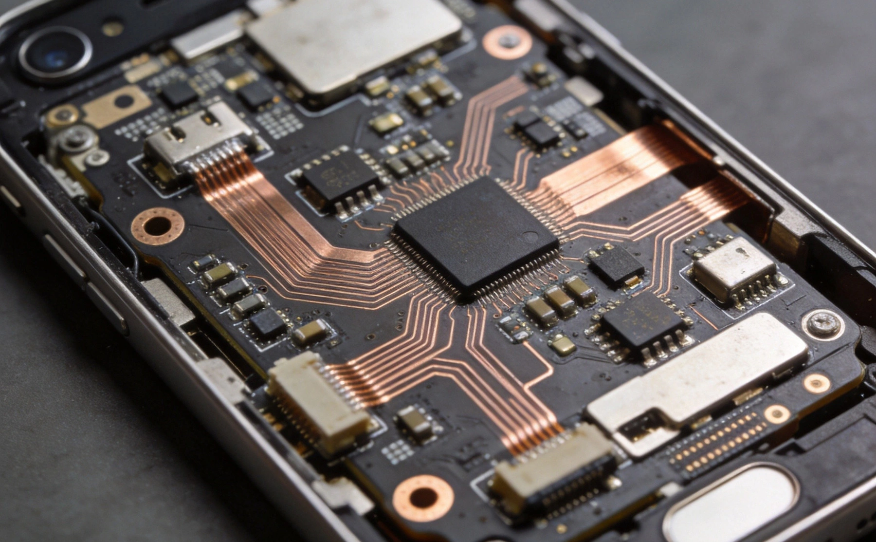
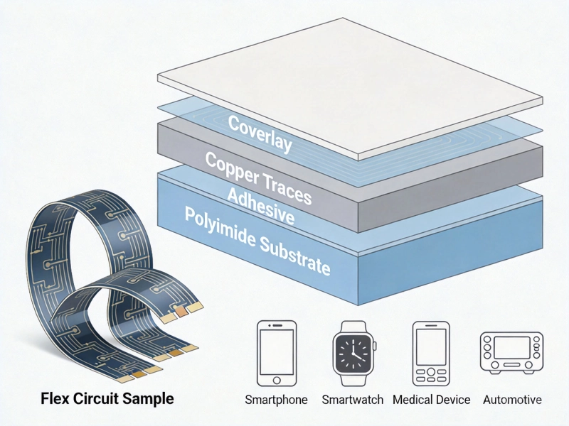
A flexible Printed Circuit Board, often shortened to Flex Pcb or FPC, is a patterned circuit assembly made using flexible insulating substrates, most commonly polyimide material. Unlike rigid PCBs that maintain a fixed shape, flex PCBs can bend, fold, twist, and conform to complex three-dimensional shapes while maintaining electrical connectivity.
Think of it like a Printed Circuit Board that works like a flexible ribbon—you can bend it thousands of times without failure, route signals across moving parts, or fit electronics into curved, uneven spaces that rigid boards simply cannot occupy.
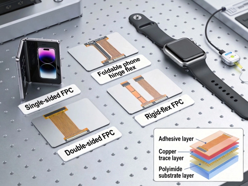
Every flex PCB consists of several key layers working together:
The unique material combination allows flex PCBs to survive repeated bending and vibration that would cause immediate failure in traditional rigid PCBs. Our manufacturing facilities produce Flex Circuits designed to survive millions of bending cycles for dynamic applications like foldable phone hinges.
Flex PCBs come in several standard configurations optimized for different applications and complexity levels:
The simplest flex PCB configuration features copper traces on one side of a Polyimide Substrate, with components mounted on the same or opposite side. Access holes can be formed through the substrate to allow component mounting on the reverse side.
Best for: Low-complexity applications, Led Lighting, simple sensor connections, low-cost consumer products
Advantages: Lowest cost, easiest to manufacture, excellent flexibility
Copper traces on both sides of the polyimide substrate, connected via plated through-holes. This configuration doubles routing density while maintaining flexibility.
Best for: Medium-complexity circuits, interconnections requiring routing on both sides, higher pin-count components
Advantages: Higher routing density, better space utilization, component mounting options on both sides
Three or more layers of circuitry stacked and laminated together, with interconnections formed through plated vias, Blind Vias, or Buried Vias. Complex designs can achieve HDI (High Density Interconnect) performance similar to rigid HDI boards.
Best for: High-complexity applications, high-density signal routing, advanced medical devices, aerospace systems
Advantages: Maximum routing density, impedance control capability, integrated shielding options
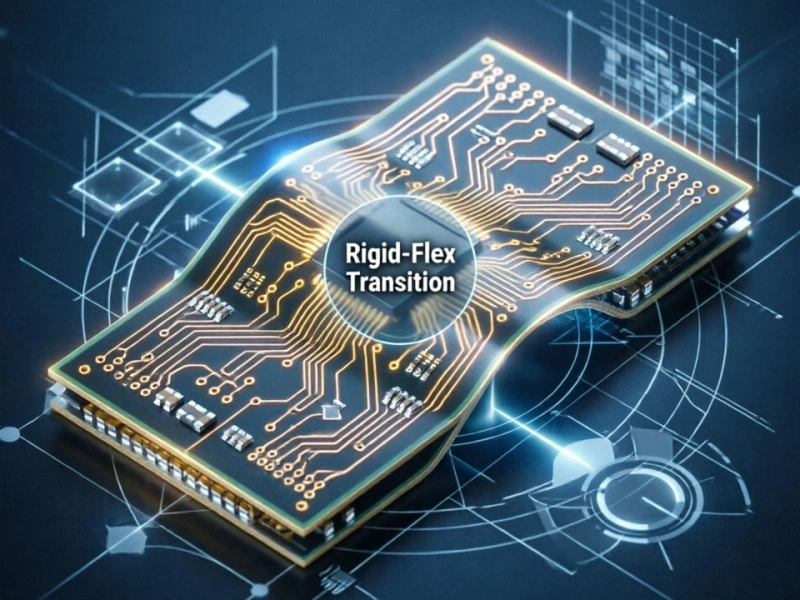
Combines Flexible Circuit layers with Rigid Pcb sections within the same assembly. The rigid sections provide mechanical support for components and connectors, while flexible sections enable bending and folding between rigid areas.
Best for: Applications requiring both component density and flexibility, medical devices, military electronics, foldable devices
Advantages: Eliminates connectors and cables between boards, reduces assembly complexity, improves reliability
Additional specialized configurations include:
Flex PCBs offer unique benefits that make them irreplaceable for many modern applications:
The most obvious advantage: flex PCBs conform to shapes, bend around corners, and fold into compact packages. This enables product designs that would be impossible with rigid boards, from foldable smartphones to curved medical implants.
We've worked with product designers who reduced their product size by 60% simply by switching from rigid boards to flex Pcb Technology. The ability to route circuits around mechanical obstacles opens up entirely new design possibilities.
Flex PCBs are significantly thinner and lighter than equivalent rigid board assemblies. A typical 2-layer flex PCB might be only 100μm thick, compared to 0.8mm for the equivalent rigid board. This weight and thickness reduction is critical for wearable devices, aerospace applications, and portable electronics where every gram matters.
Beyond the board itself, flex PCBs eliminate the need for connectors, cables, and wiring harnesses between multiple rigid boards, further reducing overall assembly weight and size.
Flex PCBs offer better reliability in harsh environments:
For applications like Automotive Electronics or aircraft systems where reliability is paramount, flex PCBs often prove more reliable than traditional rigid board assemblies.
While flex PCBs themselves cost more per unit area than rigid boards, they often reduce overall system cost:
When evaluating Total Cost Of Ownership, many companies find flex PCBs deliver net cost savings despite higher per-unit board cost.
Flex PCBs offer Signal Integrity advantages for high-speed and high-frequency applications:
For 5G devices, high-speed data interfaces, and RF applications, flex PCBs deliver superior electrical performance compared to rigid board and cable assemblies.
Flex Pcb Manufacturing differs significantly from rigid Pcb Production due to the flexible material handling requirements. Here's an overview of our standard production process:
Production begins with raw polyimide and copper foil material inspection to verify thickness, conductivity, and quality meet specifications. Materials are cut to production panel sizes with precise dimensional control. Material lot traceability is maintained throughout the process for complete quality accountability.
Photoresist is applied uniformly to the copper surface, then exposed to UV light through the circuit artwork. The exposed panel undergoes development, removing unexposed photoresist and leaving the desired circuit pattern protected.
High-resolution imaging systems with 5μm registration accuracy are essential for fine-pitch flex circuit production.
The panel passes through etching chemistry that removes unprotected copper, leaving only the desired circuit traces. Remaining photoresist is then stripped completely, leaving the bare copper circuit pattern on the polyimide substrate.
Etching process parameters are tightly controlled to ensure consistent trace width and sidewall profile, critical for impedance-controlled applications.
Adhesive-coated polyimide Coverlay is precut with openings for component pads and vias. It's then aligned to the circuit pattern and laminated under heat and pressure, permanently bonding to the board and protecting the copper traces.
Proper coverlay lamination is critical for long-term flex reliability—poor lamination leads to delamination and circuit failure under bending stress.
For double-sided and multilayer flex boards, vias are drilled mechanically or with laser systems depending on size requirements. The vias then undergo electroless copper deposition and electrolytic plating to create conductive connections between layers.
Exposed component pads receive a protective surface finish to prevent oxidation and ensure solderability. Common options for flex PCBs include:
Component designators, logos, and manufacturing markings are printed via silkscreen. If required, stiffeners are bonded to designated areas for mechanical reinforcement at connector locations or component mounting points.
Individual flex circuits are cut from production panels using one of several methods:
Every finished flex circuit undergoes 100% electrical testing using flying probe testers to verify continuity and isolation. Additional quality inspections include:
We reject any boards failing inspection, ensuring only defect-free units ship to customers. For high-reliability applications, we offer additional qualification testing including thermal cycling, humidity exposure, and bend cycle testing.
Flex PCB technology enables innovation across virtually every electronics sector:
The largest consumer of flex PCBs by volume:
We produce millions of flex circuits annually for leading consumer electronics brands, supporting the latest foldable and wearable product innovations.
Medical applications demand the highest reliability and Miniaturization:
Our medical flex Pcb Production meets Iso 13485 quality standards and supports FDA-regulated medical device production.
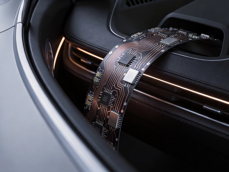
Modern vehicles increasingly rely on flex PCBs:
Automotive flex circuits must survive extreme temperature ranges, vibration, and moisture exposure for the vehicle's 10+ year lifetime.
Aerospace applications demand lightweight, high-reliability electronics:
These applications often require specialized materials and qualification testing to meet aerospace industry standards.
Industrial applications leverage flex Pcb Durability:
China has emerged as the global leader in flex Pcb Manufacturing, accounting for over 60% of global production. Here's why partnering with a China flex PCB manufacturer delivers significant advantages:
Chinese Manufacturers offer 20-40% lower pricing compared to equivalent flex PCB production in North America or Europe, while maintaining equivalent quality standards. Cost advantages come from:
These cost savings make flex technology accessible to projects that would otherwise be prohibitively expensive.
Top-tier Chinese flex PCB manufacturers have invested heavily in state-of-the-art equipment and technology, matching or exceeding capabilities available in Western facilities:
Our facilities produce high-complexity 10+ layer rigid-flex boards with HDI capabilities for leading global technology companies.
China's comprehensive Electronics Supply Chain enables seamless integration of flex PCB production with downstream assembly:
This supply chain integration translates to faster product development cycles and Time-to-market for your products.
Reputable Chinese flex PCB manufacturers maintain comprehensive quality certifications:
Quality standards have improved dramatically over the past decade, with leading Chinese Manufacturers now supplying flex circuits to the most demanding industries globally.
Experienced engineering teams provide valuable support throughout your product development cycle:
Our engineering team brings decades of flex Pcb Design experience, helping clients optimize their designs to avoid common pitfalls and ensure production success.
The bend life of a flex PCB depends on several factors: material selection, copper type, Bend Radius, and layer count. Static Flex applications (bent once during installation and never moved) can theoretically last indefinitely. Dynamic flex applications designed for repeated bending typically achieve 1,000 to 10,000,000+ cycles depending on Design Optimization. For maximum bend life, use rolled annealed copper, thicker substrates, and larger bend radii whenever possible.
The minimum safe Bend Radius depends on flex PCB thickness and construction:
These are general guidelines—always consult your manufacturer for application-specific bend radius recommendations. Bending below the minimum radius risks copper trace cracking or delamination.
Yes, flex PCBs typically cost 2-5 times more per unit area than equivalent rigid PCBs due to more complex manufacturing processes and higher material costs. However, they often reduce total system cost by eliminating connectors, cables, and assembly steps, while enabling smaller, lighter product designs with improved reliability. The total cost advantage frequently justifies the higher board cost for appropriate applications.
Polyimide is by far the most common substrate material, offering excellent thermal stability, mechanical strength, and flexibility. Specialty materials include PEN (Polyethylene Naphthalate) for lower-cost applications, PTFE (Teflon) for high-frequency applications, and specialty high-temperature polyimides for extreme environment applications. Copper is almost universally used for conductive layers, with rolled annealed copper preferred for dynamic flex applications.
A flex PCB consists entirely of flexible material throughout its structure, with optional stiffeners only in specific areas. A Rigid-flex Pcb combines sections of Flexible Circuit with rigid board sections permanently laminated together into a single assembly. Rigid-flex provides the best of both worlds: rigid sections support components and connectors for high-density assembly, while flexible sections enable bending and folding between rigid areas. Rigid-flex eliminates the need for connectors between separate rigid and flex boards, improving reliability and reducing assembly complexity.
Flexible Pcb technology has unlocked a new era of Electronics Design freedom. From foldable smartphones that fit in your pocket to life-saving medical implants that conform to human anatomy, flex circuits make the previously impossible practical.
When considering flex PCB technology for your project, focus on the total value delivered rather than just per-unit board cost. The size reduction, weight savings, improved reliability, and design flexibility often deliver far greater value than the incremental board cost. For applications requiring Miniaturization, movement, or conformance to complex shapes, flex technology is frequently the only viable solution.
As an experienced China flex PCB manufacturer, we've helped hundreds of clients successfully implement flex technology across diverse industries. Whether you're designing a simple single-sided flex circuit or a complex 10-layer rigid-flex assembly, the right manufacturing partner can make all the difference between success and costly redesigns.
Ready to explore Flexible Pcb technology for your next project? Upload your design files for a free Dfm review and quotation. Our engineering team will provide detailed feedback on manufacturability, cost optimization, and application-specific material recommendations—helping you implement flex technology successfully with no obligation.
Introduction to Flexible Printed Circuit Boards: A Practical Engineering GuideMay/18/2026

Top 5 Advantages of Using Rigid-Flex PCBs in Modern ElectronicsAugust/07/2026
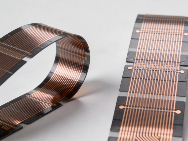
Dynamic vs. Static Flex: Which FPC Type Fits Your Project?July/20/2026
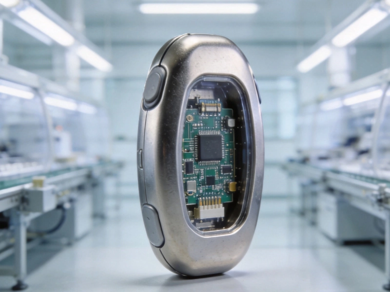
Implantable Medical Devices: Precision and Reliability in PCB ManufacturingSeptember/24/2026
Introduction to Flexible Printed Circuit Boards (FPC): Beginner's GuideMay/18/2026
Flexible PCBs in Modern Cars: Sensors, Displays, and Comfort SystemsSeptember/01/2026
Rigid-Flex PCB Design Guide: Bridging the Gap Between Rigid and FlexJuly/03/2026
Thru-Hole vs. SMT: Choosing the Right Assembly TechnologyJuly/28/2026