
Metal core PCBs represent a specialized solution for applications where Thermal Management is as critical as electrical performance. If you've ever wondered how high-power LEDs dissipate heat efficiently, how power converters maintain reliability under thermal stress, or how Automotive Electronics withstand under-hood temperatures, you're already thinking about metal core Pcb Technology.
As a China Metal Core Pcb manufacturer with over 15 years of Thermal Management experience, we've produced millions of MCPCBs for Led Lighting, Power Electronics, automotive systems, and industrial applications. This comprehensive guide will explain everything you need to know about metal core PCBs, from structure and benefits to design considerations and manufacturing.
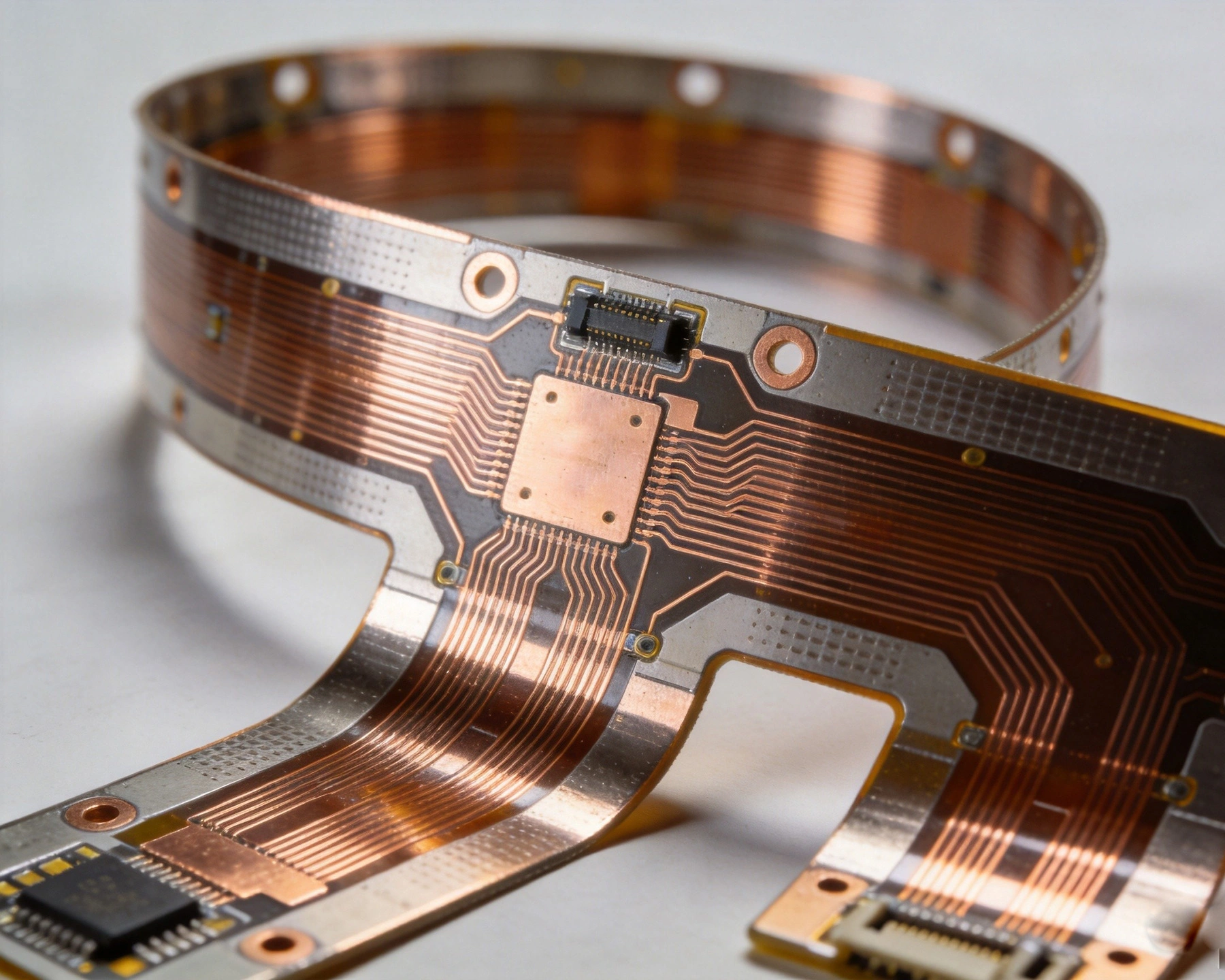
A Metal Core Pcb (Mcpcb) is a specialized Printed Circuit Board that uses a metal base material (typically aluminum or copper) as the core substrate instead of the FR-4 or other non-metallic materials used in standard PCBs. The metal core serves as a heat sink, efficiently conducting heat away from mounted components while simultaneously providing mechanical support and electrical isolation.
Think of it as a regular Circuit Board bonded to a built-in heat sink. The metal base rapidly spreads heat across the board surface, preventing hot spots that would degrade component performance and reliability. This makes MCPCBs essential for applications generating significant heat during operation.
The technology has been refined over decades since its early development for Power Electronics. Today's metal core PCBs can be single-sided or double-sided, with layer counts up to 12 layers for high-density routing—all while maintaining excellent thermal performance through the metal core substrate.
Metal core PCBs share many layers with standard PCBs but with the fundamental difference of a metallic core substrate:
The defining feature of MCPCBs is the metal core substrate that serves as the foundation and thermal management solution:
We've found that 90% of applications achieve optimal thermal performance with aluminum cores, while the most demanding power electronics require copper cores. Our engineering team can help you select the appropriate material based on your specific thermal and cost requirements.
The metal core is coated with one or more dielectric (insulating) layers that electrically isolate the conductive circuit traces from the metal core. These dielectric layers must provide:
Common dielectric materials include epoxy-based systems, polyimide for high-temperature applications, and ceramic-filled polymers for enhanced thermal performance. We've developed proprietary dielectric formulations that achieve thermal conductivity of 1.5-3.0 W/mK while maintaining full electrical isolation.
Patterned copper layers form the circuit traces carrying electrical signals, power, and ground connections. For single-sided MCPCBs, copper is etched on one side of the dielectric-coated metal core. Double-sided MCPCBs have copper circuits on both sides, connected through plated through-holes. More complex MCPCBs incorporate multiple copper layers separated by dielectric layers, enabling higher routing density and ground plane integration.
Copper Thickness varies based on current carrying requirements. Standard thicknesses include 35μm (1 oz), 70μm (2 oz), and 105μm (3 oz), with heavier copper available for power circuits requiring higher current capacity.
All our MCPCBs use rolled annealed copper for improved flexibility and reduced stress during thermal cycling compared to electrodeposited copper commonly used in low-cost applications.
Similar to standard PCBs, MCPCBs have a protective solder mask coating over the circuitry and a surface finish on exposed copper pads. Common surface finishes include Enig (Electroless Nickel Immersion Gold), Immersion Silver, Osp (Organic Solderability Preservative), and Hasl (Hot Air Solder Leveling). For high-temperature applications, we recommend Enig for its excellent thermal stability and consistent solderability.
The simplest and most common Mcpcb configuration, with circuitry on only one side of the metal core. Components mount on the circuit side, while the backside metal core remains exposed for Heat Dissipation. These boards offer the most cost-effective solution for most thermal management applications while providing excellent performance.
Typical applications: Led Lighting (both indoor and outdoor), simple power supplies, low-complexity motor drivers, basic Automotive Electronics, consumer appliances with power circuits
Advantages: Lowest cost, simplest manufacturing, excellent thermal performance, easy to design and assemble
Circuitry on both sides of the metal core, connected via plated through-holes. This configuration doubles circuit density while maintaining excellent thermal performance. Both sides can support component mounting, increasing functionality in the same footprint.
Typical applications: Complex LED driver circuits, power converters, automotive control modules with bidirectional functionality, industrial power supplies, advanced motor control systems
Design consideration: The through-hole vias must be carefully designed to maintain dielectric integrity between the copper traces and metal core while allowing electrical connections between the top and bottom copper layers.
Advantages: Higher circuit density, component mounting on both sides, better space utilization, improved design flexibility
Three or more circuit layers separated by dielectric materials, laminated with the metal core. Complex multilayer MCPCBs can achieve routing densities comparable to standard multilayer PCBs while maintaining excellent thermal performance through the metal core.
Typical applications: High-power LED displays, advanced power conversion systems, automotive ADAS electronics, industrial automation controllers, aerospace power systems
Design challenges: The lamination process must ensure dielectric layers maintain integrity during bonding and subsequent operation. Thermal expansion differences between multiple layers and the metal core must be carefully managed to prevent stress-induced failures.
Structural capabilities: Ground planes for EMI shielding, power planes for stable voltage distribution, high-density signal routing, integrated shielding structures for noise-sensitive circuits
The defining advantage of metal core PCBs is thermal management. The metal core provides exceptional heat spreading:
For high-power LED applications, MCPCBs allow up to 50% more power per board compared to standard PCBs before reaching thermal limits—this directly translates to smaller, more efficient lighting products. We've designed MCPCBs for industrial LED panels operating at 300W+ that maintain junction temperatures below 85°C.
The metal core provides significant mechanical advantages:
Automotive MCPCBs must survive 10+ years under extreme conditions including temperature cycling from -40°C to +125°C, vibration, and mechanical stress. The metal core construction inherently handles these requirements better than alternative approaches.
Lower operating temperatures dramatically improve component reliability. Most electronic components have specified maximum operating temperatures, and exceeding these temperatures accelerates failure mechanisms. Metal core PCBs:
For LED applications, this means longer warranty periods and reduced field failure rates. For power electronics, it means stable performance over extended operating lives without thermal derating.
Metal core PCBs can support complex circuit designs:
The metal core doesn't limit design complexity—rather, it enhances it by eliminating thermal constraints that would otherwise limit design options.
LED lighting is the largest consumer of metal core PCBs, accounting for over 60% of total MCPCB volume:
We produce MCPCBs for major lighting manufacturers, delivering boards supporting LED arrays up to 200W per board with thermal resistance below 0.5°C/W.
High-power electronics require robust thermal management:
In our experience, MCPCBs enable power electronics to operate at 15-25% higher power density compared to standard PCBs by maintaining lower temperatures.
Automotive environments are particularly challenging due to high ambient temperatures:
All automotive MCPCBs we produce meet Iatf 16949 automotive quality requirements and are qualified for 125°C operating temperatures.
Industrial MCPCs must survive harsh environments with dust, chemicals, temperature extremes, and vibration. The metal core construction is inherently more resistant to these environmental challenges than standard PCBs.
Metal core Pcb Manufacturing combines standard PCB processes with specialized handling for the metal core:
For double-sided MCPCBs, special attention is paid to via drilling to ensure dielectric integrity is maintained between the copper traces and metal core while creating electrical connections between the top and bottom copper layers.
Calculate required thermal resistance based on power dissipation and maximum component temperature:
We provide thermal analysis for every Mcpcb Design, calculating expected thermal resistance and recommending appropriate core thickness and design optimizations.
Metal core PCBs have specific design considerations:
We provide detailed design rules for our specific dielectric systems, helping you optimize your design for both electrical performance and manufacturability.
Thermal performance depends on the metal core material and overall board construction. Aluminum core PCBs typically achieve thermal resistance of 0.2-1.5°C/W for standard board sizes (50mm × 50mm to 100mm × 100mm), while copper core PCBs achieve 0.1-0.8°C/W. The actual thermal resistance depends on board size, core thickness, dielectric thickness, and copper distribution. Our design engineers can calculate expected thermal resistance for your specific application.
Repairing metal core PCBs is generally difficult and not recommended. The metal core and dielectric layers make rework challenging, and repair attempts often cause more damage than they fix. Minor repairs like trace rework are sometimes possible for prototypes, but for production applications, replacing damaged boards is almost always more cost-effective. We recommend proper design and manufacturing to minimize defects rather than planning for repairs.
Metal core PCBs typically cost 2-4x more per unit area than equivalent standard PCBs due to the specialized materials and processes. However, they often reduce total system cost by eliminating external heat sinks, reducing product size and complexity, and improving reliability. For thermal-critical applications, the Total Cost Of Ownership frequently shows MCPCBs as more cost-effective than standard PCBs plus separate thermal management.
Yes, metal core PCBs can support high-frequency and high-speed signals with appropriate design. The metal core actually provides EMI shielding advantages for noise-sensitive circuits. However, proper design is required to ensure Signal Integrity, particularly managing impedance and crosstalk. Our engineering team specializes in designing high-frequency MCPCBs for applications up to 10GHz and beyond.
Standard core thickness options: 1.0mm, 1.5mm, 2.0mm, 2.5mm, and 3.0mm. For LED lighting applications, 1.5mm and 2.0mm aluminum cores are most common. For power electronics and automotive applications, 2.0mm and 2.5mm cores are typical. We can produce custom thicknesses for specific applications if required.
Metal core PCBs provide an elegant solution to thermal management challenges that conventional PCBs cannot address. By integrating heat sink functionality directly into the board structure, MCPCBs enable higher power densities, improved component reliability, simplified product designs, and reduced overall system costs.
Whether you're designing an LED lighting product, power converter, automotive electronic system, or industrial equipment that generates significant heat, metal core Pcb Technology should be on your radar.
As an experienced China metal core PCB manufacturer, we've supported thousands of clients across industries in implementing MCPCB technology successfully. Our engineering team provides free Dfm reviews, thermal analysis, and design consultation to help you optimize your thermal management strategy.
Ready to implement metal core PCB technology in your next design? Upload your design files today for a free thermal analysis and quotation. Our engineering team will provide detailed feedback on core thickness selection, thermal resistance expectations, and Design Optimization specific to your application—helping you deliver thermally reliable products efficiently.
Why Your LED Lighting Project Needs an Aluminum PCBOctober/14/2026
Case Study: Solving a Complex Thermal Issue with a Metal Core PCBOctober/12/2026
Heavy Copper PCB Etching: Challenges, Tolerances, and Precision SolutionsSeptember/10/2026
What is the Minimum Trace Width for HDI PCBs?July/17/2026
How to Prevent Common Failures in Flexible Circuit DesignSeptember/09/2026
Why Automotive Electronics Demand High-Reliability Multilayer PCBsJuly/13/2026
Top 5 Advantages of Using Rigid-Flex PCBs in Modern ElectronicsAugust/07/2026
How to Design High-Layer Count PCBs (20+ Layers) for Complex ElectronicsSeptember/08/2026