
Modern radar systems and satellite communication networks depend heavily on specialized electronic components that can operate at extremely high frequencies. At the heart of these systems lies the high-frequency Printed Circuit Board—a critical enabling technology that determines whether a defense contractor's radar array or a telecom operator's satellite ground station performs reliably under demanding conditions. The gap between a functioning prototype and a field-deployable system often comes down to the quality and design sophistication of the high-frequency PCBs inside.

Most consumer electronics rely on FR4 substrate materials, which offer adequate performance up to approximately 1 GHz. When defense engineers design radar systems operating at 10 GHz, 24 GHz, or even 77 GHz for automotive safety systems, standard materials introduce unacceptable levels of signal loss and unpredictable impedance variations. The dielectric properties of conventional FR4 fluctuate with temperature and humidity—exactly the environmental conditions encountered in outdoor radar installations and satellite uplinks.
Beyond electrical performance, these applications demand boards that maintain structural integrity under thermal cycling. A satellite experiences extreme temperature swings as it transitions between direct sunlight and Earth's shadow, with surface temperatures ranging from minus 150 degrees Celsius to plus 150 degrees. The PCB substrate must handle thousands of such cycles without developing cracks or delamination that would compromise signal routing.
Military specifications add another layer of complexity. Defense contracts frequently require compliance with MIL-PRF-31032 or MIL-PRF-55110 standards, which mandate specific material certifications, traceability documentation, and testing protocols. Working with a manufacturer who understands these requirements prevents costly redesign cycles and delayed program milestones.
High-frequency Pcb Manufacturing starts with selecting the right base material. Rogers Corporation produces benchmark materials like RO4003C and RO4350B that offer stable dielectric constants across wide frequency ranges. These hydrocarbon ceramic composites deliver loss tangents below 0.003 at 10 GHz—roughly ten times better than standard FR4 at the same frequency.
Taconic provides alternative options such as RF-35 and TLY-5, which balance cost considerations with performance requirements. For applications at millimeter-wave frequencies above 30 GHz, companies increasingly turn to ceramic-filled substrates like Rogers RO3000 series materials, which maintain consistent impedance even at 77 GHz automotive radar frequencies.
Material choice affects every aspect of the Manufacturing Process. Rogers materials require different lamination parameters, drilling conditions, and plating procedures compared to FR4. A manufacturer experienced with high-frequency materials knows that Rogers boards need extended desmear times during via preparation and specialized handling procedures to prevent surface contamination that could affect RF performance.
Radar systems transmit and receive signals that must maintain precise amplitude and phase relationships. Even small impedance deviations—variations exceeding plus or minus 5 percent on 50-ohm transmission lines—create signal reflections that reduce effective range and resolution. Achieving tight Impedance Tolerance requires careful attention to trace geometry, substrate thickness consistency, and copper roughness.
Signal Integrity engineers calculate trace widths based on the substrate's effective dielectric constant, accounting for the electromagnetic field distribution between the trace and ground plane. For coupled structures like edge-coupled differential pairs, the spacing between traces becomes as critical as the individual trace widths. Design software with integrated electromagnetic simulation helps predict actual performance before fabrication.
Through-hole vias create discontinuities in high-frequency signal paths. The via barrel introduces parasitic capacitance and inductance that become increasingly problematic at higher frequencies. RF designers often specify blind or Buried Vias to minimize transition lengths, or they implement via fencing—rows of grounded vias surrounding signal vias—to control electromagnetic coupling.
Via-in-pad technology, where component leads connect directly into the plated via barrel, eliminates the need for annular rings and reduces inductive discontinuities. However, this approach requires specialized fill and plating processes that not all manufacturers support reliably. A Turnkey PCB Assembly provider with RF expertise can advise on whether the cost premium for via-in-pad delivers measurable performance benefits for a particular application.
Effective grounding in high-frequency PCBs differs fundamentally from digital circuit grounding. RF grounds must provide low-inductance paths at the frequencies of interest, which often means using solid metal core constructions or multilayer boards with extensive ground plane coverage. Slot antennas and unintended radiation become real concerns when ground planes contain gaps or interrupted stitching.
Power-handling capability creates another design constraint. Radar transmitters often include power amplifier modules that dissipate significant heat. The PCB must conduct this heat away through thermal vias to external heatsinks or cold plates. Material thermal conductivity—typically 0.3 to 0.5 watts per meter-Kelvin for Rogers materials versus 0.3 for FR4—influences whether additional Thermal Management measures are necessary.
Confirming that a fabricated board meets RF specifications requires testing equipment and methods beyond standard electrical verification. Time-domain reflectometry identifies impedance discontinuities along transmission paths, while vector network analyzers measure S-parameters that characterize insertion loss, return loss, and phase response across the frequency band of interest.
Manufacturers often provide impedance test coupons—dedicated test structures fabricated alongside production panels—that customers can measure to verify process capability. These coupons should be specified in the fabrication drawing, along with acceptable Impedance Tolerance windows. Acceptance criteria for military or aerospace applications typically require 100 percent impedance testing on critical nets.
Thermal testing validates material performance under extended high-power operation. Accelerated life testing subjects samples to temperature cycling while monitoring for changes in electrical parameters. Material datasheets provide guidance on glass transition temperatures and decomposition temperatures, but actual system reliability depends on the specific stackup construction and operating conditions.
Producing high-frequency PCBs reliably requires investment in specialized equipment, trained personnel, and documented quality systems. Not every Contract Manufacturer with Smt Assembly capability can deliver RF boards that perform consistently at 10 GHz or above. When evaluating potential partners, request sample impedance data from recent high-frequency orders and ask about their experience with specific materials like Rogers or Taconic.
Documentation practices matter significantly for defense contracts. Look for manufacturers who maintain complete traceability from raw material certificates through fabrication steps to final test data. Automated Optical Inspection and laser measurement systems that generate quantitative reports provide the evidence that auditors and program managers require.
Lead time expectations differ from standard Pcb Production. High-frequency materials often require longer delivery times due to specialized lamination cycles and extended processing for vias. Building a relationship with a capable manufacturer early in the design cycle allows for design-for-manufacturing feedback that can reduce costs and improve first-pass yield.
What frequency range do high-frequency PCBs typically support?
Specialized high-frequency materials like Rogers RO4000 series can reliably operate from audio frequencies through 40 GHz and beyond. Standard high-frequency grades typically target applications from 1 GHz to 20 GHz, while advanced ceramic substrates support millimeter-wave applications at 60 GHz and 77 GHz for automotive radar.
How do High-frequency Pcb costs compare to standard FR4 boards?
High-frequency materials typically cost three to eight times more than FR4 on a per-panel basis, depending on the specific material grade and order volume. The total cost impact depends on board complexity, layer count, and tolerance requirements. However, the performance benefits often justify the premium when system specifications cannot be met with standard materials.
Can high-frequency PCBs be assembled with standard SMT processes?
Yes, with appropriate process adjustments. High-frequency substrates often have different thermal properties than FR4, requiring modified reflow profiles. Components can be placed using standard equipment, but the assembly process should be qualified for the specific substrate material. A turnkey provider experienced with RF boards can optimize the assembly process accordingly.
What is the typical impedance tolerance for high-frequency applications?
Tolerance requirements depend on the application. Consumer applications typically accept plus or minus 10 percent on 50-ohm lines. Defense and aerospace systems often require plus or minus 5 percent or tighter. Some critical RF paths may need plus or minus 2 percent tolerance, which requires careful Stackup Design and statistical process control during fabrication.
How do I specify High-frequency Pcb requirements for manufacturing?
Your fabrication drawing should include the material specification (for example, Rogers RO4350B), thickness and tolerance requirements, copper weight on signal and plane layers, impedance specifications with tolerance windows for critical nets, and any special requirements like blind/Buried Vias or via-in-pad construction. Including a cross-sectional drawing helps ensure the manufacturer understands your stackup intent.
High-frequency PCBs represent a specialized domain where material science, precision manufacturing, and RF engineering intersect. Radar and satellite communication systems place demanding requirements on board materials, fabrication precision, and assembly quality that go well beyond standard commercial electronics. Success in these applications depends on selecting appropriate materials like Rogers or Taconic, partnering with manufacturers who understand the unique processing requirements of high-frequency substrates, and specifying clear acceptance criteria that can be verified objectively.
Whether developing next-generation phased array radar for defense applications or designing satellite ground station electronics for telecommunications infrastructure, investing the effort to get high-frequency PCB specifications right from the start prevents costly redesigns and ensures field reliability.
Why Medical Devices Require Specialized High-Reliability PCB ManufacturersSeptember/15/2026
Common DFM Mistakes in Rigid-Flex PCB Layouts: A Comprehensive GuideJuly/29/2026
Selecting a High-Speed PCB Manufacturer for 5G TelecommunicationsAugust/13/2026
Controlled Impedance Testing: Ensuring Performance in High-Speed BoardsOctober/15/2026
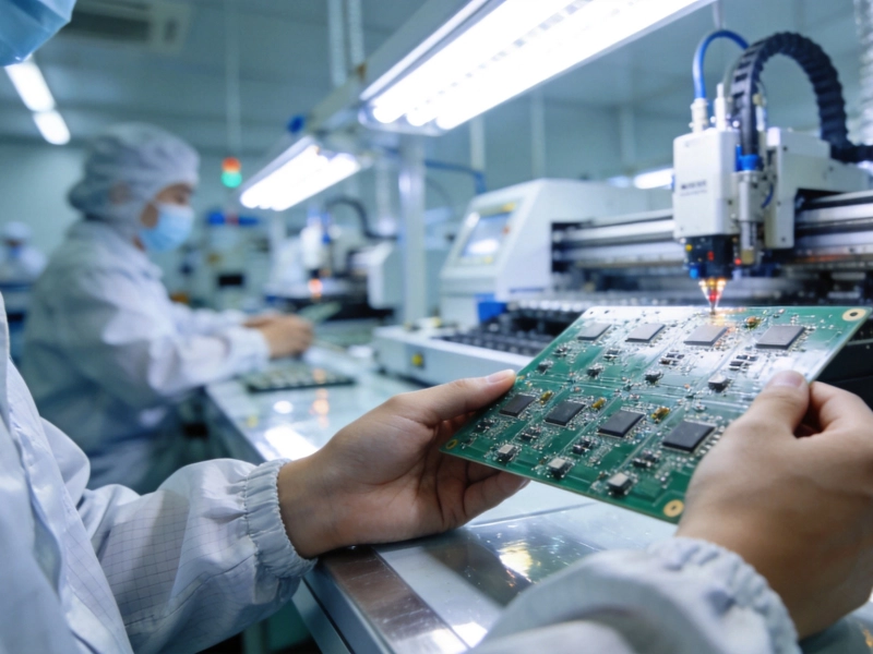
What to Look for in a Reliable SMT PCB Assembly Partner in ChinaAugust/11/2026
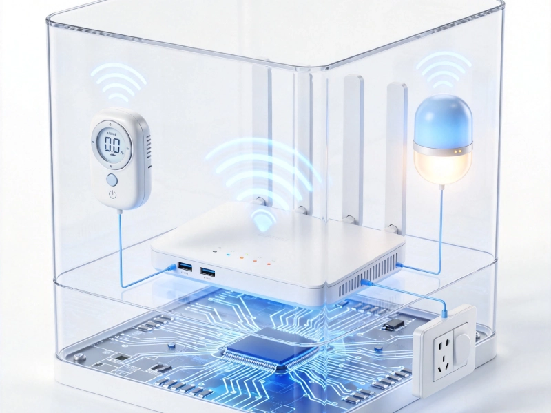
Smart Home Devices: Integrating High-Frequency PCBs for Wi-Fi/BluetoothSeptember/21/2026

Why Automotive Electronics Demand High-Reliability Multilayer PCBsJuly/13/2026
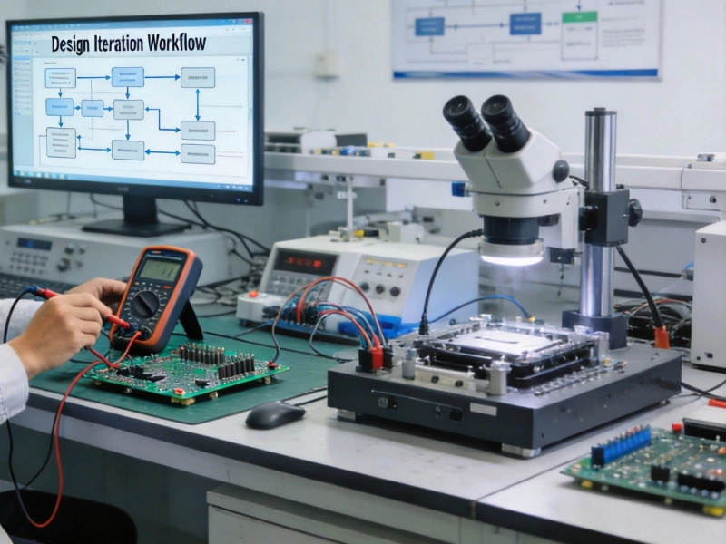
PCB Prototype Manufacturing in China: Complete GuideMay/18/2026