
Automotive lighting has undergone a fundamental transformation over the past decade. Halogen bulbs have given way to high-intensity discharge (HID) lamps, and now LED technology dominates new vehicle designs across every segment from entry-level compacts to luxury sedans. This shift has created new engineering demands that traditional PCB substrates simply cannot satisfy. LED headlight assemblies require boards that can move significant heat away from the light source rapidly and reliably, year after year, across extreme temperature ranges and sustained vibration. Metal core PCBs have become the definitive solution for this application, and sourcing them requires a specialized approach that differs substantially from standard PCB procurement.
For engineers and procurement professionals tasked with finding manufacturing partners for automotive LED headlight PCBs, the complexity can be daunting. Thermal requirements, material certifications, automotive quality standards, and cost pressures converge to create a demanding supplier qualification challenge. This guide walks through the critical factors to evaluate when sourcing metal core PCBs for automotive LED applications.
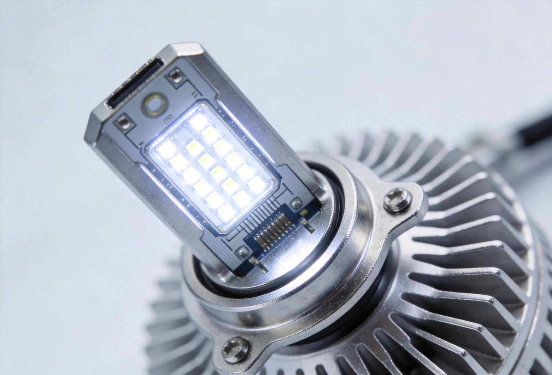
LEDs convert electrical energy into light far more efficiently than incandescent sources, but the fraction of energy that does not become light becomes heat. High-power automotive LEDs used in headlight applications can generate significant thermal loads that must be dissipated to maintain junction temperatures within specified limits. Exceeding these limits dramatically shortens LED lifespan and can cause color shift, reduced output, and catastrophic failure.
Traditional FR-4 epoxy glass substrates have thermal conductivity of approximately 0.3 W/mK, meaning heat accumulates at the LED junction rather than spreading to the surrounding environment. Metal core PCBs (MCPCBs) solve this problem by incorporating a metal base—typically aluminum or copper—that conducts heat away from the LED attachment point with thermal conductivity ranging from 1 to 8 W/mK depending on the specific construction.
The metal base acts as a heat spreader, distributing thermal energy across a larger surface area where it can transfer to the housing, heat sink, or surrounding structure. This Thermal Management capability is not optional for automotive LED headlights. Every major automotive LED headlight manufacturer specifies MCPCBs in their designs precisely because conventional substrates cannot support the thermal performance these systems demand.
Metal core PCBs for LED applications typically use one of several constructions, each with distinct characteristics and trade-offs. Understanding these variations is essential for specifying your requirements accurately to potential suppliers.
The most common construction places a dielectric insulation layer between the copper circuit layer and the metal base. This dielectric layer provides electrical isolation while maintaining thermal conductivity. The thermal resistance of this dielectric layer often dominates the overall thermal path, making dielectric material selection a critical design decision. Common dielectric materials include polyimide, thermally conductive epoxies, and ceramic-filled composites.
Some LED applications use metal-clad laminates where the dielectric is replaced by a thin direct-bonded copper (DBC) or active metal brazed (AMB) ceramic layer. These constructions offer superior thermal conductivity but at significantly higher cost. For most automotive headlight applications, standard dielectric-based MCPCBs provide adequate thermal performance with more favorable economics.
Flex-to-install designs are common in headlight modules where the Mcpcb must conform to a curved surface or fit within a complex housing geometry. These designs incorporate a Flexible Circuit section that transitions to the rigid metal core region under the LED array. Designing for flex-to-install requires careful attention to Bend Radius limits and the thermal cycling implications of flex-to-rigid junctions.
Sourcing MCPCBs for automotive LED headlights demands deep collaboration between the LED module designer and the PCB manufacturer. Thermal performance cannot be evaluated in isolation—it depends on the interaction between the LED package, the thermal interface materials, the Mcpcb, and the mechanical housing.
Request thermal simulation data from your PCB supplier. The best manufacturers use thermal analysis tools to model heat flow through the board stackup and predict junction temperatures under your specific operating conditions. Ask to see this analysis early in the qualification process, and verify that the simulation assumptions align with your actual thermal environment.
Thermal vias play an important role in transferring heat from the component side of the board to the metal base. The density, diameter, and plating quality of thermal vias directly affect thermal resistance. Your CM should provide clear specifications for thermal via arrays, including annular ring requirements, plating thickness standards, and any fill or cover options. Unfilled thermal vias can trap contaminants during assembly, so confirm the supplier's via treatment process.
Consider whether your design requires thermal simulation under dynamic conditions. Automotive headlights cycle between ambient temperatures and operating temperatures repeatedly throughout a vehicle's life. Thermal cycling can degrade thermal interface materials and solder joints over time. A qualified supplier should be able to provide guidance on thermal fatigue considerations and recommend design accommodations.
Automotive applications impose stringent material certification requirements that go well beyond what consumer electronics specify. The International Automotive Task Force (IATF) 16949 standard governs Quality Management systems for automotive suppliers, and compliance is typically a minimum requirement for any supplier serving original equipment manufacturers (OEMs) or tier-one automotive suppliers.
Beyond Iatf 16949, specific materials used in the MCPCB must meet automotive-grade specifications. The dielectric material must demonstrate stable electrical and thermal properties across the full operating temperature range, typically -40°C to +125°C or wider for under-hood proximity applications. Request material data sheets and automotive compliance documentation from your supplier.
ROHS and REACH compliance is mandatory for all Automotive Electronics sold in major markets. Confirm that your supplier maintains current compliance documentation and that all materials in their standard MCPCB construction meet these directives. Some automotive OEMs impose additional substance restrictions beyond ROHS, so clarify whether any such requirements apply to your program.
The metal base material itself—almost always aluminum for LED headlight applications—must meet specifications for purity, alloy composition, and mechanical properties. Aluminum 5052 and 6061 are common choices, with 5052 offering better formability for complex geometries and 6061 providing higher strength. Specify your material requirements clearly to avoid receiving inconsistent constructions across production lots.
Automotive LED headlight MCPCBs demand inspection rigor that matches their demanding operating environment. Visual defects that would be acceptable in consumer applications may be unacceptable for safety-critical automotive lighting.
Request the supplier's defect classification system and accept quality limit (AQL) standards. World-class automotive suppliers typically operate to AQL levels of 0.10% or tighter for critical characteristics. For safety-critical attributes such as dielectric thickness, insulation resistance, and thermal via integrity, 100% inspection may be required rather than sampling.
Electrical testing should include hipot testing (dielectric withstand voltage) at levels appropriate for Automotive Electronics, typically 500V DC or higher depending on the system voltage architecture. Insulation resistance testing verifies dielectric integrity, while continuity testing confirms circuit connectivity. For high-voltage LED driver circuits, confirm that the supplier's test equipment and procedures match your voltage requirements.
Cross-sectional analysis provides definitive verification of internal construction quality. This destructive test method reveals dielectric thickness, layer adhesion, thermal via plating quality, and solder joint integrity. Request microsection data from initial production samples and periodically during ongoing production to verify process stability.
The transition from design intent to producible MCPCB requires careful attention to manufacturing constraints specific to metal core construction. Experienced suppliers will flag design issues during the Dfm review, but early awareness of these constraints helps you avoid costly redesigns.
Minimum feature sizes differ from standard rigid PCBs. Via diameters, trace widths, and spacing capabilities depend on the specific metal core construction and the supplier's equipment capabilities. Confirm these limits early in the design phase to avoid over-specifying tolerances that no manufacturer can consistently achieve.
Panel utilization affects unit cost significantly. Metal core PCBs are generally produced in smaller panel sizes than standard FR-4 boards due to equipment constraints. Understanding the supplier's standard panel sizes and designing for efficient panel utilization reduces piece price substantially.
Edge margin requirements for metal core PCBs are typically larger than for standard boards due to the machining processes used to create panel rails and depanelization. Specify your dimensional tolerances with awareness that metal core construction has wider achievable tolerances than advanced HDI rigid boards. If your design requires tight dimensional control, discuss this with your supplier to determine whether it is achievable or whether tolerance relaxation is necessary.
China hosts a substantial portion of the world's MCPCB manufacturing capacity, including many facilities with deep experience in automotive LED applications. Sourcing from Chinese Manufacturers can provide significant cost advantages and access to specialized expertise, but effective qualification is essential to ensure quality and reliability.
Look for suppliers with established automotive programs. A manufacturer currently serving tier-one automotive customers for Led Lighting applications has already demonstrated the quality systems, process controls, and documentation practices that automotive programs require. Ask for reference programs and verify their scope, duration, and quality performance.
Request a thorough qualification package from prospective suppliers. This should include FAI (first article inspection) results, production part approval process (PPAP) documentation, process capability studies for critical characteristics, and measurement system analysis (MSA) reports for key inspection equipment. Suppliers unfamiliar with these automotive qualification requirements may need guidance, which can delay programs and introduce risk.
Consider the Total Cost Of Ownership, not just unit price. Logistics, quality risk, communication overhead, and potential rework or warranty costs all factor into the true cost of MCPCB sourcing. The lowest unit price frequently does not represent the best overall value when automotive quality requirements and supply continuity risks are properly accounted for.
Automotive programs typically run for many years, with design freezes that make component substitution expensive and time-consuming. Choosing a supplier with stable manufacturing capacity, sustainable financial health, and long-term market commitment protects your program from supply disruption.
Evaluate the supplier's financial stability and market position. Electronics Manufacturing is capital-intensive and competitive, with consolidation occurring regularly. A supplier experiencing financial stress may cut corners on materials, equipment maintenance, or quality staff, creating risk for your program. Prioritize partners with demonstrated financial health and clear strategic direction.
Buffer stock agreements help protect against supply volatility. Work with your supplier to establish appropriate safety stock levels and replenishment protocols that balance inventory carrying cost against supply continuity risk. For automotive programs, having several months of buffer inventory for long-lead components is prudent.
Build relationships with multiple contacts at your chosen supplier, including engineering, quality, and program management. Personnel turnover is a reality in any industry, and having established relationships across functions provides resilience when individuals change roles. Regular communication—even when there are no urgent issues—maintains these relationships and surfaces potential problems before they become crises.
Sourcing metal core PCBs for automotive LED headlights demands rigorous attention to thermal design, material certification, quality standards, and supplier qualification. The complexity of these requirements reflects the demanding environment in which automotive lighting must perform reliably for the lifetime of the vehicle. By approaching supplier selection with the same engineering rigor applied to the LED module design itself, you can identify partners capable of delivering the quality and reliability that automotive customers expect.
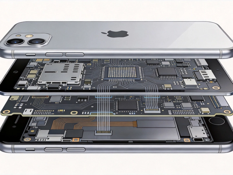
How HDI PCBs Enable Slimmer Smartphones and TabletsJune/26/2026
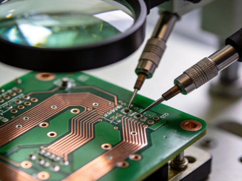
How to Verify the Quality of a PCB Prototype Before Mass ProductionOctober/13/2026
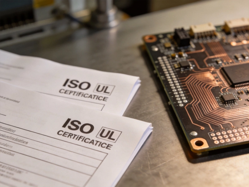
ISO and UL Certifications: What They Mean for Your PCB QualitySeptember/26/2026
ISO and UL Certifications: What They Mean for Your PCB QualitySeptember/23/2026
How to Specify Bend Radius for Flexible PCB OrderAugust/06/2026

Supply Chain Resilience: Why Diversifying with a China PCB Partner HelpsSeptember/04/2026
Common DFM Mistakes in Rigid-Flex PCB Layouts: A Comprehensive GuideJuly/29/2026
How to Prevent Common Failures in Flexible Circuit DesignSeptember/09/2026