Open Nav

Flexible Printed Circuit Boards (FPCs, also called flex PCBs) have evolved from a specialized niche technology to a foundational component of modern Electronics Design. According to industry reports, the global Flexible Pcb market will exceed $20 billion by 2027, driven by demand for foldable devices, Wearable Technology, Automotive Electronics, and 5G infrastructure. For engineering teams, understanding FPC technology is no longer optional—it's essential for building competitive, high-performance products.
As a China-based Fpc Manufacturer with 12+ years of production experience serving over 500 clients across 30 countries, we've prepared this practical introduction to help engineering teams understand FPC fundamentals, make informed design decisions, and avoid common pitfalls that lead to costly delays or quality issues.
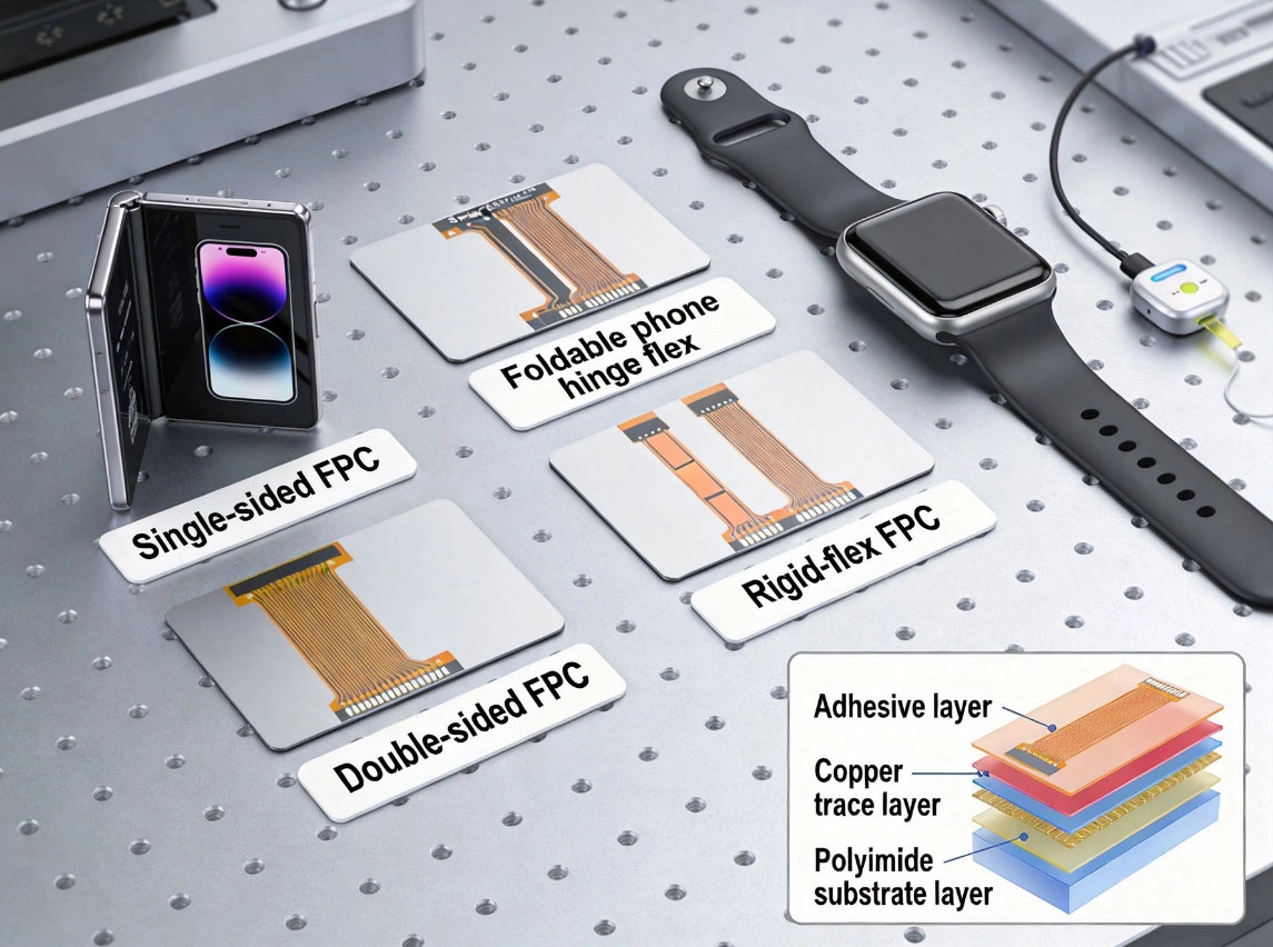
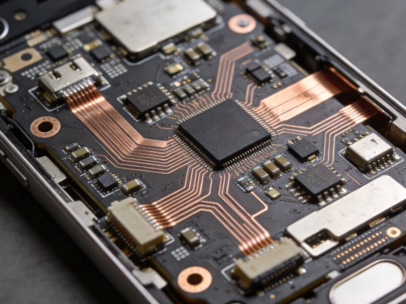
Flexible Printed Circuit Boards are patterned electronic assemblies constructed using thin, bendable polymer substrates instead of the rigid fiberglass-reinforced epoxy used in traditional PCBs. Unlike rigid boards that maintain a fixed form factor, FPCs can be bent, folded, twisted, or dynamically flexed millions of times while maintaining reliable electrical connectivity.
The technology dates back to the 1950s when it was first developed for military aerospace applications, but has since become mainstream across consumer, medical, automotive, and industrial sectors. Modern FPCs can match the circuit density of rigid HDI boards while delivering unique mechanical advantages no rigid technology can match.
At their core, all FPCs combine four essential functional layers:
Beyond these basics, FPCs can incorporate additional layers including shielding for EMI protection, stiffeners for mechanical reinforcement, and Thermal Management layers for high-power applications. This design flexibility makes FPCs adaptable to an incredibly wide range of use cases.
The performance of any Flexible Pcb depends almost entirely on material selection. Understanding material properties helps you make optimal choices for your specific application requirements:
Polyimide (PI) is the industry standard substrate for 90% of FPC applications, offering an unbeatable combination of properties:
Polyethylene Naphthalate (PEN) is a lower-cost alternative to polyimide for cost-sensitive applications that don't require extreme temperature resistance. PEN has a maximum operating temperature of ~150°C, making it unsuitable for reflow soldering processes. It's commonly used in low-cost consumer electronics and Static Flex applications.
Liquid Crystal Polymer (LCP) is a high-performance material for high-frequency and millimeter-wave applications. It offers extremely low dielectric loss and stable electrical properties across wide temperature and frequency ranges, making it ideal for 5G mmWave antenna systems and radar applications. LCP costs significantly more than standard polyimide but delivers unmatched RF performance.
Specialty substrates include transparent polyimides for flexible displays, flame-retardant grades for automotive applications, and radiation-resistant grades for aerospace and nuclear environments.
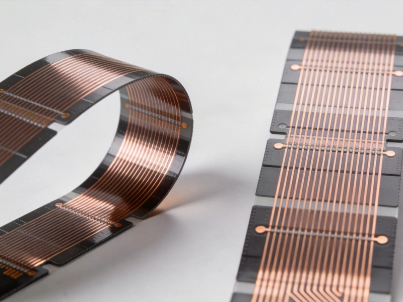
Electrodeposited (ED) Copper is the standard conductive material for most Static Flex applications. It offers good electrical conductivity at lower cost, but has lower ductility making it less suitable for Dynamic Flex applications requiring repeated bending.
Rolled Annealed (RA) Copper is manufactured through a rolling and annealing process that produces a more ductile grain structure. It offers 2-5x better flex fatigue resistance compared to ED copper, making it essential for Dynamic Flex applications like foldable phone hinges that will see millions of bend cycles. RA copper typically costs 20-30% more than ED copper but prevents premature trace cracking in high-cycle applications.
Specialty conductive materials include aluminum for lightweight applications, copper alloys for high-strength requirements, and silver traces for high-frequency or high-conductivity applications.
Acrylic adhesives are the most common bonding material for standard FPCs, offering good adhesion strength and flexibility at moderate cost. They have operating temperatures up to ~125°C, sufficient for most consumer applications.
Epoxy adhesives offer higher temperature resistance and stronger bond strength, making them suitable for automotive and industrial applications requiring extended reliability under harsh conditions.
Coverlay is the protective layer used on most FPCs, typically made of polyimide film pre-coated with adhesive. It offers superior flexibility compared to solder mask, which is only used on rigid sections of rigid-flex boards or low-flex applications.
Flexible Printed Circuit boards come in five primary configurations optimized for different design requirements:
The simplest configuration, with copper traces on only one side of the substrate. Components can be surface-mounted on either the copper side or reverse side through access holes. Single-sided FPCs represent ~60% of total FPC production volume due to their low cost and simplicity.
Typical applications: Led Lighting strips, simple sensor interconnections, keypad circuits, low-cost consumer electronics, battery interconnects
Design advantages: Lowest cost, thinnest profile, maximum flexibility, simplest Manufacturing Process
Copper traces on both sides of the substrate, connected through plated through-holes. This configuration doubles routing density while maintaining full flexibility. Surface-mount components can be placed on either side for maximum space utilization.
Typical applications: Camera modules, display interconnects, medium-complexity sensor systems, laptop hinge circuits
Design advantages: Higher routing density, component placement flexibility, better space utilization
Three or more layers of patterned copper laminated together, with interconnections through plated vias, Blind Vias, or Buried Vias. High-density multilayer FPCs can achieve routing densities comparable to rigid HDI boards while retaining full flexibility.
Typical applications: Advanced medical devices, aerospace systems, high-speed signal routing, complex wearable electronics
Design advantages: Maximum routing density, Controlled Impedance capability, integrated EMI shielding, high circuit complexity
Hybrid construction combining Flexible Circuit sections with Rigid Pcb regions permanently laminated into a single assembly. The rigid sections provide mechanical support for components, connectors, and high-density circuitry, while flexible sections enable bending and folding between rigid areas. Rigid-flex technology eliminates the need for connectors and cables between separate rigid and flex assemblies.
Typical applications: Foldable smartphones, military electronics, medical devices, aerospace systems, high-reliability industrial controls
Design advantages: Eliminates connector failure points, reduces assembly complexity, improves reliability, reduces overall size and weight by up to 40% compared to traditional rigid board assemblies
Specialized FPCs with varying thickness across the board, achieved through selective etching or Sequential Lamination. Thicker regions provide mechanical stiffness where needed, while thinner regions maintain maximum flexibility in bend areas. This premium configuration is used for high-performance applications requiring optimized mechanical properties.
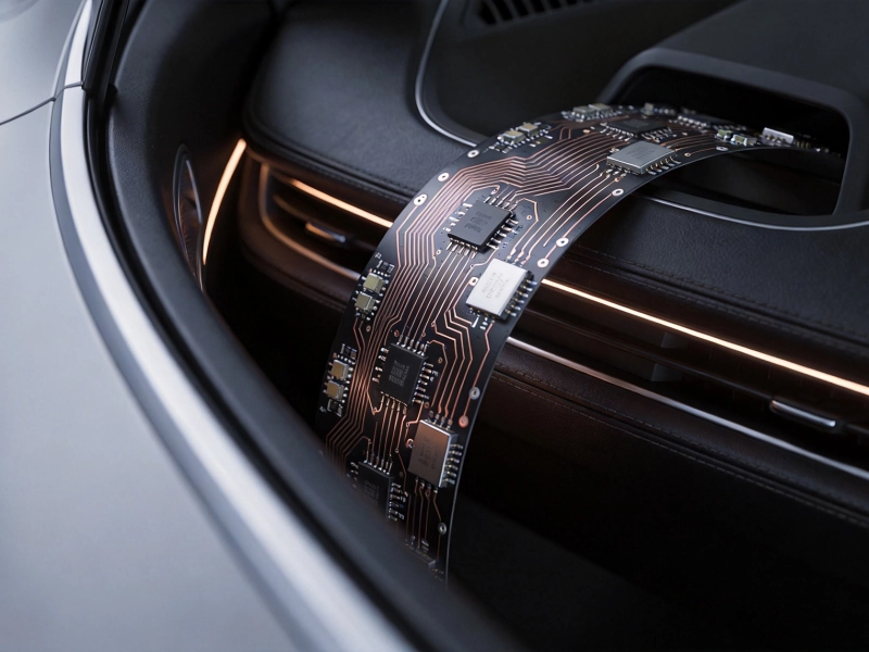
Typical applications: Automotive Electronics, aerospace systems, dynamic flex applications with complex mechanical requirements
Design advantages: Optimized stiffness/flexibility across the board, improved mechanical reliability, reduced overall assembly thickness
Choosing between flexible PCBs, rigid PCBs, and flexible flat cables (FFCs) depends on your specific design priorities. Use this decision framework for initial evaluation:
In practice, many modern products combine multiple technologies: rigid PCBs for high-density component mounting, FPCs for interconnections between boards, and FFCs for simple, high-volume internal connections.
Proper design is critical for FPC reliability and manufacturing success. Based on our experience with thousands of FPC designs, follow these core guidelines:
Quality Control for FPCs requires specialized testing beyond what's used for rigid PCBs. Reputable manufacturers perform these standard tests:
Common FPC failure modes include copper trace cracking in bend areas, delamination between layers, via plating failures, and coverlay adhesion issues. Proper material selection, Design Optimization, and manufacturing Quality Control prevent nearly all these failures.
FPC technology continues to evolve rapidly to support emerging applications:
These innovations will expand FPC applications even further in coming years, making Flexible Electronics an increasingly essential technology across all industries.
FPC pricing depends primarily on four factors: layer count, material selection, manufacturing complexity, and order volume. Multilayer rigid-flex designs with specialty materials cost significantly more than simple single-sided FPCs. Order volume also has a dramatic impact—prototypes may cost 5-10x more per unit than high-volume production due to fixed setup and tooling costs. Material selection can increase cost by 20-200% depending on whether you use standard polyimide or specialty materials like LCP.
When evaluating FPC manufacturers, consider these key factors: relevant industry experience in your application sector, quality certifications (Iso 9001, Iatf 16949 for automotive, Iso 13485 for medical), in-house testing capabilities, engineering support for Dfm reviews, and consistent on-time delivery performance. Request references from clients in your industry and ask to see quality data including defect rates and yield performance.
The most frequent design errors we see include: bending below the minimum recommended radius, placing traces or vias in bend areas, not accounting for material shrinkage during lamination, insufficient Copper Thickness for current requirements, and poor pad design leading to solder joint failures. These mistakes are almost entirely avoidable with proper Dfm Review from an experienced manufacturer early in the design process.
Properly designed and manufactured FPCs can operate in extremely harsh environments. Standard polyimide FPCs operate from -40°C to +125°C, while high-temperature grades can withstand continuous operation up to 260°C. Specialized FPCs are available for radiation environments (space applications), high humidity, corrosive chemical exposure, and extreme vibration. Always specify your environmental requirements to your manufacturer during the design phase.
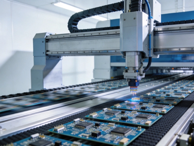
Standard lead times vary by complexity: single/double-sided FPC prototypes take 5-7 business days, multilayer FPCs take 7-10 days, and complex rigid-flex designs take 10-15 days. Production quantities typically add 2-5 days depending on volume. Expedited services are available for time-critical projects, reducing lead times by 30-50% for an additional cost.
Flexible Printed Circuit boards have transitioned from a specialized technology to a mainstream design option enabling the most innovative electronics products on the market. Understanding FPC fundamentals, material properties, design guidelines, and manufacturing considerations empowers engineering teams to leverage this technology effectively.
While FPCs require more careful design consideration than traditional rigid PCBs, the benefits in size reduction, weight savings, reliability improvement, and design flexibility often justify the additional investment. The most successful FPC implementations involve close collaboration between design teams and manufacturers early in the development process, optimizing designs for both performance and manufacturability.
As Flexible Electronics continue to evolve, FPC technology will enable entirely new product categories that were impossible with traditional rigid board technology. Whether you're designing a simple sensor interconnect or a complex multilayer rigid-flex assembly for aerospace applications, FPC technology offers capabilities no other electronics packaging approach can match.
Ready to implement flexible printed circuit boards in your next design? Our engineering team offers free, no-obligation DFM reviews and feasibility assessments for FPC designs of any complexity. Upload your design files today and get expert guidance on material selection, cost optimization, and reliability improvement for your specific application requirements.
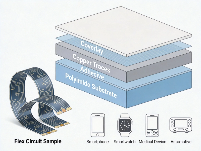
Introduction to Flexible Printed Circuit Boards (FPC): Beginner's GuideMay/18/2026

Top 5 Advantages of Using Rigid-Flex PCBs in Modern ElectronicsAugust/07/2026
Implantable Medical Devices: Precision and Reliability in PCB ManufacturingSeptember/24/2026
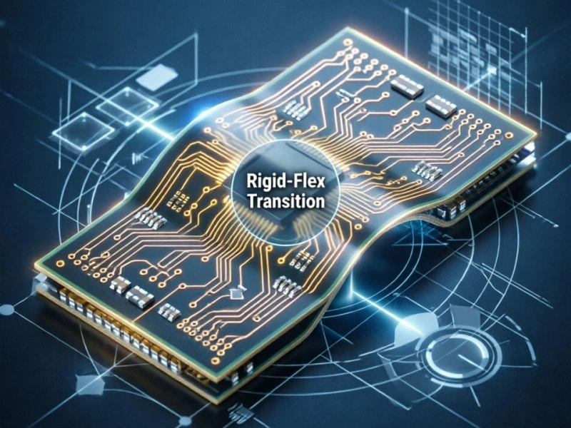
Rigid-Flex PCB Design Guide: Bridging the Gap Between Rigid and FlexJuly/03/2026
What is Flexible PCB? Complete Guide from China Flex PCB ManufacturerMay/18/2026
Flexible PCBs in Modern Cars: Sensors, Displays, and Comfort SystemsSeptember/01/2026
Dynamic vs. Static Flex: Which FPC Type Fits Your Project?July/20/2026
Bridging the Gap: Moving from PCB Prototype to Mass ProductionOctober/09/2026