Open Nav

If you're new to Electronics Design or manufacturing, you've likely encountered both rigid printed circuit boards (PCBs) and their more flexible counterparts—Flexible Printed Circuit Boards, often shortened to FPC or flex PCBs. These innovative circuits have transformed how we design electronics, enabling everything from foldable smartphones to life-saving medical devices.
This introduction is written specifically for beginners, with no prior specialized knowledge required. We'll break down what Flexible Printed Circuit Boards are, how they work, their core benefits, common types, and where they're used across industries. By the end, you'll have a solid foundational understanding of this transformative technology.
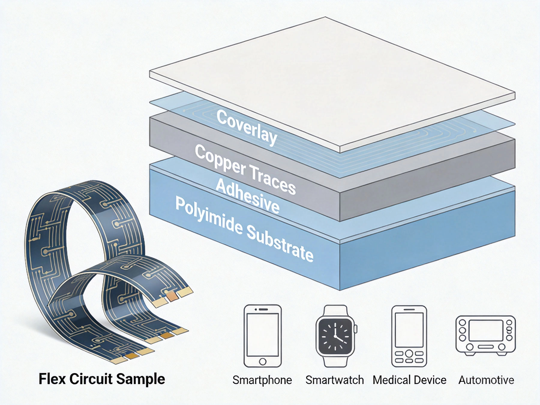
Flexible Printed Circuit boards are patterned electronic assemblies made using thin, flexible insulating substrates (most commonly polyimide film) instead of the rigid fiberglass used in traditional PCBs. Unlike rigid boards that hold a fixed shape, Flex Circuits can bend, fold, twist, and conform to complex three-dimensional spaces while maintaining reliable electrical connections.
Think of them as the flexible ribbon cables you might find inside a laptop connecting the display to the motherboard, but with all the same circuit density and functionality as rigid boards. They can be as simple as a single layer of copper traces on polyimide, or as complex as 10+ layer rigid-flex assemblies combining both rigid and flexible sections.
The technology has existed for decades but has become increasingly common as consumer demand for smaller, lighter, more portable electronics has grown. Today, Flexible Printed Circuit boards are found in nearly every modern electronic device you use daily.
While designs vary significantly by complexity, all flexible printed circuit boards share the same core layered structure:
The foundation of every flex circuit is the substrate, a thin polymer film that provides mechanical flexibility and electrical insulation. Polyimide is by far the most common substrate material due to its excellent combination of properties:
Typical substrate thickness ranges from 12.5μm (0.0005") for ultra-flexible applications up to 125μm (0.005") for more rigid flex designs. Lower-cost applications sometimes use PEN (Polyethylene Naphthalate) film instead of polyimide, though it has lower temperature resistance.
The conductive layer consists of thin Copper Foil laminated to the substrate, which is etched to form the circuit traces carrying electrical signals. Two types of copper are commonly used:
Copper Thickness typically ranges from 18μm to 70μm, with thicker copper used for higher-current applications.
A specialized adhesive bonds the Copper Foil to the Polyimide Substrate. Flex circuit adhesives are formulated to maintain bond strength even under repeated bending, temperature cycling, and environmental exposure.
The Coverlay is a protective layer laminated over the etched copper circuit, serving the same purpose as solder mask on rigid PCBs:
Coverlay is typically made of the same polyimide material as the substrate, coated with adhesive, and pre-punched with openings for component pads and connectors before lamination.
Additional optional features include:
Flexible printed circuit boards are categorized by their layer count and construction:
The simplest and most common type, with copper traces on only one side of the Polyimide Substrate. Components can be mounted on either the copper side or the reverse side through access holes in the substrate.
Best for: Low-complexity applications, Led Lighting, simple interconnections, high-volume cost-sensitive products
Advantages: Lowest cost, thinnest profile, maximum flexibility
Copper traces on both sides of the substrate, connected via plated through-holes. This configuration doubles routing density while maintaining flexibility.
Best for: Medium-complexity circuits, designs requiring higher component density, interconnections that need routing on both sides
Advantages: Higher routing density, more design flexibility, component mounting options on both sides
Three or more layers of circuitry laminated together, with interconnections through plated vias, Blind Vias, or Buried Vias. High-density designs can achieve HDI (High Density Interconnect) performance similar to rigid HDI boards.
Best for: High-complexity applications, advanced medical devices, aerospace systems, high-speed signal routing
Advantages: Maximum routing density, impedance control capability, integrated EMI shielding options
A hybrid construction that combines Flexible Circuit layers with Rigid Pcb sections permanently laminated into a single assembly. Rigid sections provide mechanical support for components and connectors, while flexible sections enable bending and folding between rigid areas.
Best for: Applications requiring both high component density and flexibility, foldable electronics, military systems, medical devices
Advantages: Eliminates connectors and cables between separate boards, reduces assembly complexity, improves reliability, reduces overall size and weight
Compared to traditional rigid PCBs and wiring harnesses, Flex Circuits offer several unique benefits:
Flex circuits can be shaped, bent, folded, and routed to fit the available space inside a product, rather than requiring the product to be designed around the Circuit Board. This enables product form factors that would be impossible with rigid boards, from curved wearable devices to foldable smartphones.
Flex circuits are significantly thinner and lighter than equivalent rigid board assemblies. A typical 2-layer flex circuit might be only 0.1mm thick, compared to 0.8mm for the equivalent rigid board. This weight and thickness reduction is critical for aerospace, wearable, and portable electronics applications where every gram counts.
Beyond the board itself, flex circuits eliminate the need for connectors, cables, and wiring harnesses between multiple rigid boards, further reducing overall assembly size and weight.
Flex circuits offer better reliability in harsh environments:
For applications like Automotive Electronics or aircraft systems where reliability is paramount, flex circuits often prove more reliable than traditional rigid board assemblies.
While flex circuits themselves cost more per unit area than rigid PCBs, they often reduce total system cost:
When evaluating Total Cost Of Ownership, many companies find flex circuits deliver net cost savings despite higher per-unit board cost.
Flex circuits offer Signal Integrity advantages for high-speed and high-frequency applications:
For 5G devices, high-speed data interfaces, and RF applications, flex circuits deliver superior electrical performance compared to rigid board and cable assemblies.
Flexible printed circuit boards are used across virtually every electronics sector:
While flex Pcb Manufacturing shares some similarities with rigid Pcb Production, it requires specialized processes to handle the flexible materials:
Specialized handling equipment is required throughout the process to prevent damage to the thin, flexible materials.
If you're considering using flexible printed circuit boards for your first project, keep these basic guidelines in mind:
Never bend a flex circuit tighter than its recommended minimum Bend Radius, which depends on thickness and construction:
Bending below these minimum values risks cracking copper traces or causing delamination that will lead to circuit failure.
The lifespan depends on the application and operating conditions. Static Flex applications (bent once during installation and never moved) can last 10+ years under normal conditions. Dynamic flex applications designed for repeated bending typically achieve 1,000 to 10,000,000+ cycles depending on Design Optimization and material selection. Properly designed and manufactured flex circuits have demonstrated lifespans exceeding 20 years in static aerospace and automotive applications.
Repairing flex circuits is generally difficult and not recommended for most applications, especially high-reliability uses. Small trace repairs can sometimes be performed with conductive epoxy or micro-soldering, but these repairs reduce reliability and are only suitable for prototype or low-volume applications. For production designs, it's almost always more cost-effective to replace a damaged flex circuit rather than attempt repair.
Standard flex circuits are not inherently waterproof, though their polyimide substrate is moisture-resistant. For applications requiring waterproofing, flex circuits can be coated with conformal coatings, encapsulated in waterproof polymers, or housed in sealed enclosures. Special materials and manufacturing processes can produce water-resistant flex circuits suitable for medical devices and consumer electronics requiring IP ratings.
FPC (Flexible Printed Circuit) refers to etched flex circuits with patterned copper traces as described in this guide. FFC (Flexible Flat Cable) is a simpler product consisting of flat copper conductors sandwiched between two layers of polymer film, with no patterning or complex circuitry. FFCs are lower cost for simple, high-volume interconnection applications, but lack the design flexibility and circuit density of FPCs.
Yes, flex circuits can handle high currents with appropriate design. Current Carrying Capacity depends on Copper Thickness, trace width, and Heat Dissipation. Thicker copper traces (35μm to 70μm or more) are used for higher current applications. Thermal Management considerations include providing sufficient copper area for Heat Dissipation and avoiding tight bends in high-current traces that might increase resistance. For very high-current applications, specialized heavy copper flex circuits are available.
Flexible printed circuit boards have come a long way from their early military applications, becoming an essential technology enabling the modern electronics revolution. As demand for smaller, lighter, more capable electronics continues to grow, flex circuit technology will only become more widespread.
For designers and product developers, understanding the basics of flexible printed circuit boards opens up entirely new design possibilities. Whether you're creating a wearable device, medical instrument, automotive system, or consumer product, flex circuits offer capabilities no other technology can match.
As you explore using flex circuits for your projects, remember to partner with an experienced manufacturer early in the design process. Their expertise will help you avoid common pitfalls, optimize your design for cost and reliability, and bring your innovative product concepts to life.
Ready to start your first flex circuit project? Our engineering team offers free Dfm reviews and design guidance for beginners. Upload your design requirements today for a no-obligation consultation and quotation—we're here to help you succeed with flexible printed circuit technology.

Top 5 Advantages of Using Rigid-Flex PCBs in Modern ElectronicsAugust/07/2026
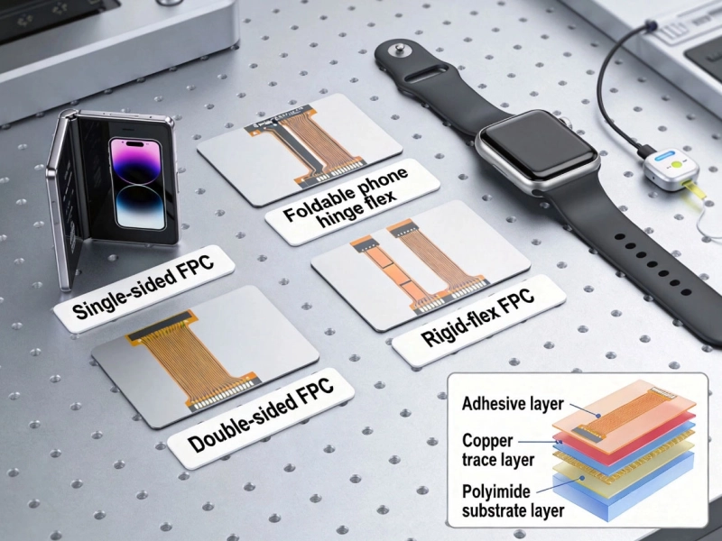
Introduction to Flexible Printed Circuit Boards: A Practical Engineering GuideMay/18/2026
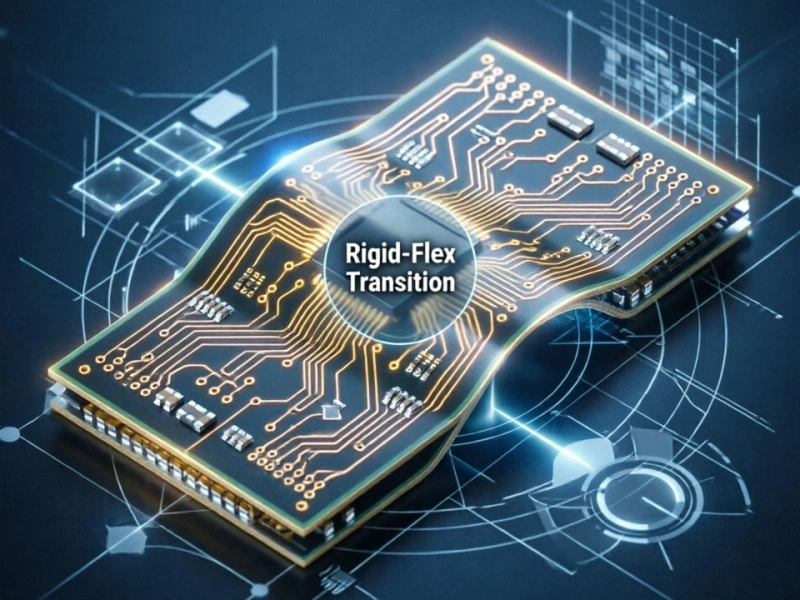
Rigid-Flex PCB Design Guide: Bridging the Gap Between Rigid and FlexJuly/03/2026
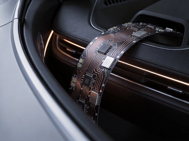
Flexible PCBs in Modern Cars: Sensors, Displays, and Comfort SystemsSeptember/01/2026
Implantable Medical Devices: Precision and Reliability in PCB ManufacturingSeptember/24/2026
Dynamic vs. Static Flex: Which FPC Type Fits Your Project?July/20/2026
What is Flexible PCB? Complete Guide from China Flex PCB ManufacturerMay/18/2026
Common DFM Mistakes in Rigid-Flex PCB Layouts: A Comprehensive GuideJuly/29/2026