Open Nav

Thermal Management is one of the most critical challenges in modern high-power electronic design. As component densities increase and power requirements rise, traditional Printed Circuit Board (PCB) materials like FR4 often struggle to dissipate heat efficiently, leading to premature component failure, reduced performance, and costly warranty claims. This case study explores how a custom Metal Core Pcb (Mcpcb) solution solved a persistent overheating issue for an industrial Led Lighting manufacturer, delivering measurable performance improvements and significant business value.
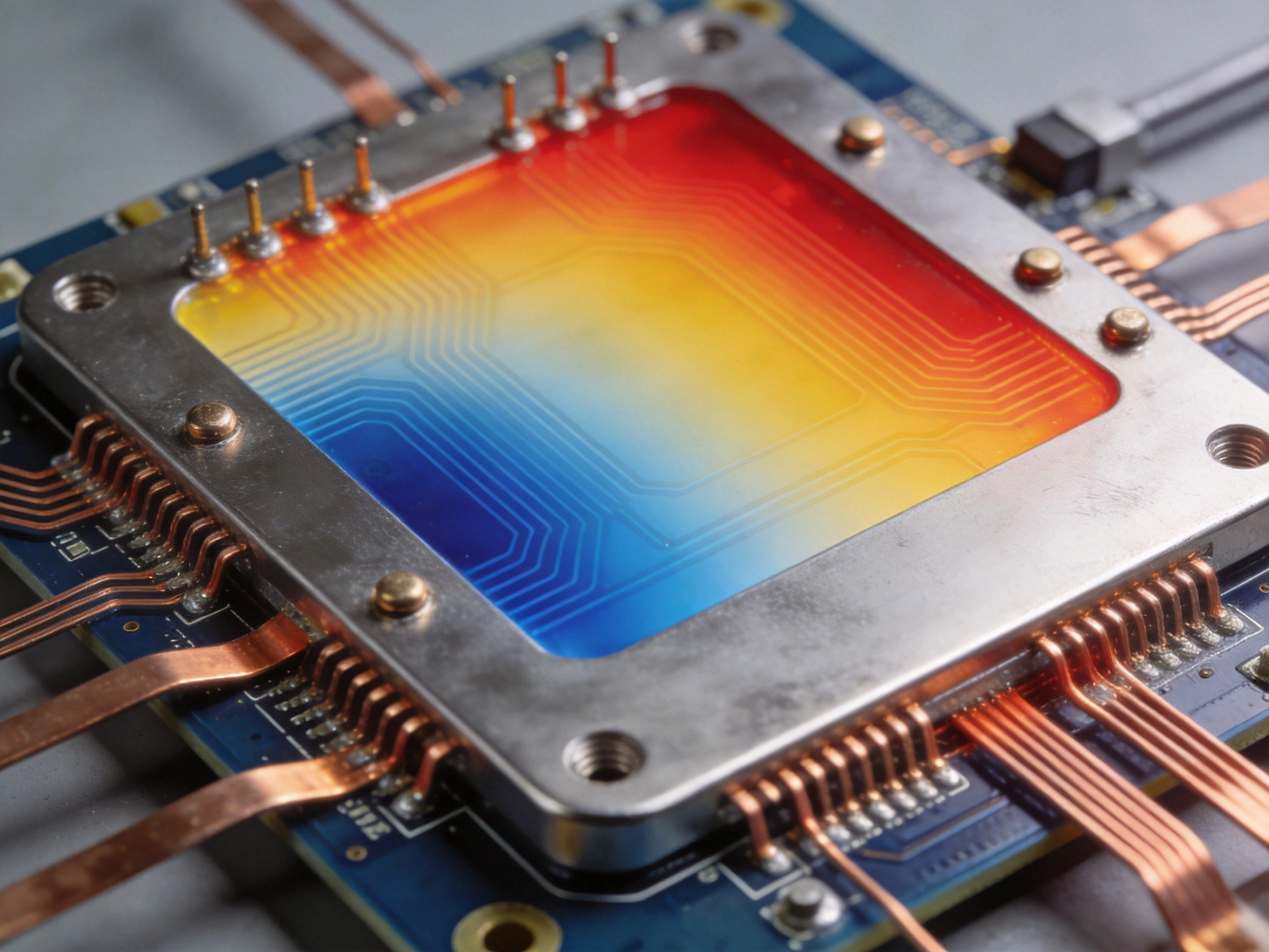
Our client, a leading manufacturer of industrial high-bay Led Lighting solutions for warehouse and manufacturing facilities, was facing a critical reliability issue with their flagship 150W LED fixture line. Despite multiple design iterations, the product was experiencing a 30% field failure rate within 12 months of deployment, primarily due to overheating of the LED packages.
The original design used a standard 1.6mm thick FR4 PCB to mount the LED array. Under continuous operation at full power, thermal imaging tests revealed LED junction temperatures reaching 128°C, far exceeding the LED manufacturer's maximum rated operating temperature of 85°C. This excessive heat caused accelerated lumen degradation, color shift, and complete LED failure in thousands of units deployed across North America.
The business impact was substantial: the company was spending $2.4M annually on warranty claims, customer retention had dropped 18% year-over-year, and the product line was at risk of being discontinued if the issue could not be resolved within 6 months. The engineering team had already attempted several conventional solutions without success:
Our engineering team conducted a comprehensive thermal analysis of the existing design to identify the root cause of the overheating issue. We used finite element analysis (FEA) thermal simulation software combined with physical temperature testing of production units to map heat flow throughout the fixture assembly.
The analysis revealed that the FR4 PCB was acting as a significant thermal bottleneck. FR4, the most common PCB substrate material, has a thermal conductivity of only 0.3 W/mK, meaning it is a relatively poor conductor of heat. Heat generated by the LED packages could not move quickly through the FR4 substrate to the external heatsink, causing it to accumulate at the LED junctions.
Temperature distribution measurements across the PCB surface showed a maximum temperature difference of 72°C between the hottest LED locations and the coolest areas near the mounting holes. This uneven heating created thermal stress on the solder joints, leading to premature joint failure and further reducing product reliability.
We concluded that the only way to resolve the issue without compromising the product's performance, environmental rating, or cost structure was to replace the FR4 PCB with a custom Metal Core Pcb specifically optimized for thermal performance.
Our team developed a custom Mcpcb Design tailored to the client's specific application requirements. The design was optimized to maximize Heat Dissipation while maintaining electrical insulation, mechanical stability, and compliance with all relevant industry standards.
Key design decisions included:
The final design was fully compliant with RoHS, REACH, and UL 94V-0 flame retardant requirements, matching all regulatory certifications of the original product.
Before full production deployment, we conducted extensive testing to validate the performance and reliability of the new Mcpcb Design:
All test results met or exceeded the client's performance requirements, confirming that the MCPCB design had fully resolved the overheating issue.
The implementation of the custom metal core PCB delivered significant improvements in both product performance and business outcomes for our client:
This case study demonstrates the significant value that custom metal core PCBs can deliver for high-power electronic applications where Thermal Management is critical. Based on our experience with this and similar projects, we recommend considering MCPCB solutions when:
For best results, we recommend involving Pcb Design engineers with thermal management expertise early in the product development process. Thermal simulation should be performed during the initial design phase to identify potential bottlenecks before physical prototypes are produced, reducing development time and cost.
If you're facing thermal management challenges with your high-power Pcb Design, our team of experienced engineers can help you evaluate if a metal core PCB is the right solution for your application. Contact us to discuss your requirements.
What is Metal Core PCB? Complete Guide from China ManufacturerMay/18/2026
Why Your LED Lighting Project Needs an Aluminum PCBOctober/14/2026
What is Flexible PCB? Complete Guide from China Flex PCB ManufacturerMay/18/2026
Need It Fast? The Benefits of a Quick Turn PCB Manufacturer in ChinaJune/16/2026
ISO and UL Certifications: What They Mean for Your PCB QualitySeptember/26/2026
Introduction to Flexible Printed Circuit Boards: A Practical Engineering GuideMay/18/2026
Top 5 Applications of HDI PCBs in Modern ElectronicsMay/13/2026
How to Reduce Your PCB Manufacturing Costs Without Sacrificing QualityJuly/08/2026