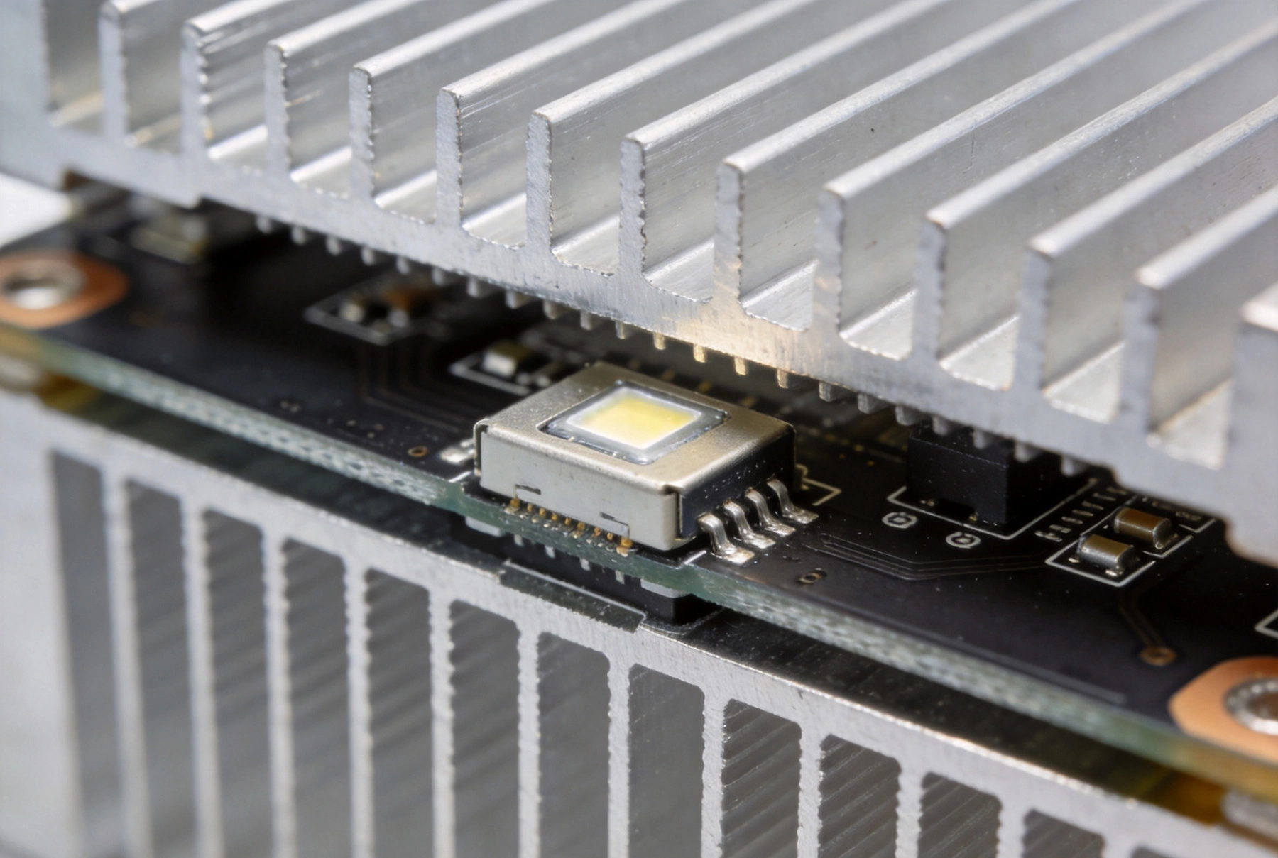
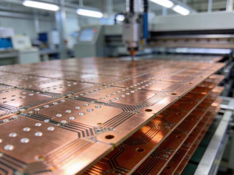
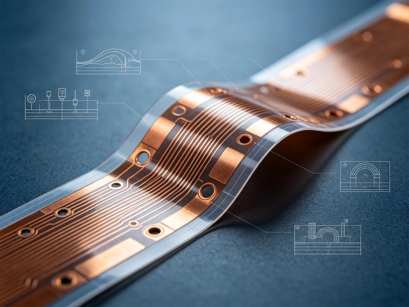
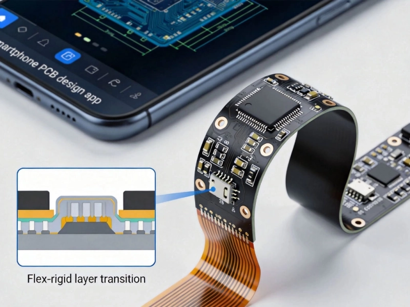
High-power electronic components generate significant heat that standard FR-4 PCBs simply cannot dissipate efficiently. Metal Core Printed Circuit Boards (MCPCBs), also known as Insulated Metal Substrate (IMS) boards or metal-backed PCBs, solve this problem by replacing the traditional fiberglass-epoxy substrate with a metal core that provides dramatically superior thermal conductivity. The two most common metal core materials—aluminum and copper—each offer distinct advantages and trade-offs that make them suitable for different applications. Understanding the fundamentals of MCPCBs and the differences between these two substrate options is essential for designing reliable, thermally efficient high-Power Electronics.

What Is a Metal Core PCB (MCPCB)?
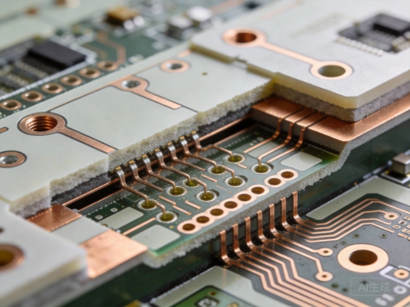
An Mcpcb consists of three primary layers that work together to provide both electrical functionality and Thermal Management:
- Circuit Layer (Top): A standard Copper Foil layer (typically 1-10 oz) where circuit traces and component pads are etched, identical to the copper layer on a conventional PCB.
- Dielectric/Insulating Layer (Middle): A thin thermally conductive but electrically insulating layer that prevents short circuits between the copper circuit layer and the metal core while allowing heat to pass through. This layer is the critical performance bottleneck, as its thermal conductivity determines how effectively heat transfers from components to the metal core. Modern high-performance dielectric layers achieve thermal conductivity of 1-3 W/m·K, compared to only 0.3-0.4 W/m·K for standard FR-4.
- Metal Core/Base Layer (Bottom): A thick metal plate (typically 0.5-3.0mm) that acts as a heat spreader and radiator, distributing heat across a large area and dissipating it to the surrounding environment. This layer also provides mechanical rigidity, reducing board flexing that could stress solder joints.
In addition to the standard three-layer structure, some Mcpcb designs use multiple circuit layers separated by dielectric and metal layers, or incorporate the metal core as an integral ground plane with direct component attachment (copper coin technology) for maximum thermal performance.
Aluminum Core PCBs: The Workhorse of Metal Core Designs
Aluminum is the most widely used metal core material, offering an excellent balance of thermal performance, cost, manufacturability, and mechanical properties.
Key Properties of Aluminum Substrates
- Thermal Conductivity: 130-230 W/m·K (alloy-dependent), roughly 500-900 times better than FR-4's 0.25-0.3 W/m·K
- Density: 2.7 g/cm³, lightweight compared to copper
- Coefficient of Thermal Expansion (CTE): 23 ppm/°C, reasonably matched to PCB copper and component materials
- Yield Strength: 35-280 MPa depending on alloy and temper, providing good mechanical rigidity
- Cost: Relatively low, widely available in standard alloy grades (5052, 6061, 6063)
Advantages of Aluminum Core MCPCBs
- Cost-Effective Thermal Management: Aluminum MCPCBs typically cost 20-40% more than equivalent FR-4 boards but are significantly less expensive than copper core alternatives, making them the most economical choice for most high-power applications.
- Light Weight: At roughly one-third the density of copper, aluminum cores are ideal for weight-sensitive applications such as automotive Led Lighting, portable electronics, and aerospace systems.
- Excellent Manufacturability: Aluminum is easy to machine, drill, punch, and shear using standard metalworking equipment, supporting high-volume production with consistent quality.
- Good Thermal Performance: For the majority of high-power applications, aluminum provides sufficient thermal conductivity to keep component junction temperatures within safe operating limits.
- Natural Corrosion Resistance: Aluminum forms a protective oxide layer that provides inherent corrosion resistance, although anodizing or protective coatings are often applied for additional protection in harsh environments.
- Proven Track Record: Aluminum MCPCBs have been used in high-volume production for over two decades, with well-characterized reliability and extensive manufacturing experience across the industry.
Common Applications for Aluminum Core MCPCBs
- Led Lighting: High-power LED modules for automotive headlights, street lighting, industrial lighting, and horticulture lighting. The aluminum core spreads heat from densely packed LED chips, maintaining light output and extending LED lifespan.
- Power Electronics: Motor drives, DC-DC converters, and power supply modules where thermal management is critical for MOSFET and IGBT reliability.
- Automotive Electronics: LED lighting controllers, battery management systems, and power converters for electric and hybrid vehicles.
- Consumer Electronics: High-brightness display backlighting, audio amplifiers, and power adapters requiring compact, efficient thermal management.
- Solar Power Electronics: Inverters and maximum power point tracking (MPPT) controllers that operate at high power densities in outdoor environments.
Copper Core PCBs: Maximum Thermal Performance
Copper core MCPCBs are used when aluminum cannot provide sufficient thermal performance for the most demanding high-power applications.
Key Properties of Copper Substrates
- Thermal Conductivity: 385-401 W/m·K, roughly twice that of aluminum and 1,500 times better than FR-4
- Density: 8.9 g/cm³, approximately 3.3 times heavier than aluminum
- Coefficient of Thermal Expansion (CTE): 17 ppm/°C, closer to silicon (2.6 ppm/°C) and ceramic component values, reducing thermomechanical stress
- Yield Strength: 70-220 MPa depending on alloy and temper
- Cost: 2-4 times more expensive than aluminum cores
Advantages of Copper Core MCPCBs
- Superior Thermal Conductivity: Copper's thermal conductivity is roughly double that of aluminum, enabling more efficient heat spreading and lower component junction temperatures for the same power dissipation.
- Better CTE Match: Copper's lower coefficient of thermal expansion is closer to that of silicon and ceramic components, reducing thermomechanical stress on solder joints during temperature cycling and improving long-term reliability.
- Higher Current Capacity: Copper cores can carry significantly higher electrical currents, beneficial when the metal core is used as an integral power or ground conductor.
- Superior Magnetic Shielding: Copper provides better electromagnetic shielding for sensitive circuits in close proximity to high-power switching components.
- Copper Coin/Embedded Copper Technology: Localized copper coins can be embedded in aluminum or FR-4 boards to provide concentrated thermal pathways under specific high-power components, combining the cost benefits of aluminum with the thermal performance of copper where it matters most.
Common Applications for Copper Core MCPCBs
- High-Power RF and Microwave: Power amplifiers for base stations, Radar Systems, and broadcast transmitters that generate extreme heat in compact footprints.
- High-Power LED Modules: Ultra-high-power LED arrays exceeding 100W per module for specialty lighting, projection systems, and medical illumination where aluminum cannot maintain acceptable junction temperatures.
- Power Semiconductor Modules: High-current IGBT and MOSFET modules for motor drives, welding equipment, and power converters operating at extreme power densities.
- Automotive Power Electronics: EV/HEV power inverters and on-board chargers where the combination of high power density, thermal cycling, and reliability requirements favors copper cores.
- Defense and Aerospace: Radar transceivers, electronic warfare systems, and satellite power electronics that require maximum thermal performance and reliability.
Head-to-Head Comparison: Aluminum vs. Copper
- Thermal Conductivity: Copper (385-401 W/m·K) delivers roughly 2x the thermal conductivity of aluminum (130-230 W/m·K), resulting in 25-40% lower component junction temperatures for the same design.
- Weight: Aluminum is approximately 3x lighter than copper for the same core thickness. For a 1.5mm core, aluminum weighs roughly 4.05 kg/m² vs. copper's 13.35 kg/m².
- Cost: Aluminum core MCPCBs typically cost 40-60% less than equivalent copper core boards, due to both lower raw material cost and easier manufacturability.
- CTE Compatibility: Copper's CTE (17 ppm/°C) is better matched to silicon and ceramic components than aluminum's (23 ppm/°C), reducing thermal cycling stress on solder joints by approximately 25-35%.
- Manufacturability: Aluminum is significantly easier to machine, drill, and process than copper, supporting higher production throughput and lower manufacturing costs.
- Corrosion Resistance: Aluminum naturally forms a protective oxide layer; copper requires protective coatings (plating, lacquer) to prevent oxidation and corrosion.
Choosing the Right Metal Core for Your Application
The choice between aluminum and copper substrates should be based on a systematic evaluation of your thermal requirements, cost constraints, and application conditions:
When to Choose Aluminum
- Component power dissipation is moderate (1-10W per component) and can be managed with aluminum's thermal conductivity
- Cost sensitivity is a primary concern, especially for high-volume consumer or automotive applications
- Weight is a critical design factor (automotive, aerospace, portable devices)
- The application involves moderate thermal cycling with CTE mismatch within acceptable limits
- High-volume manufacturability and supply chain availability are important
When to Choose Copper
- Component power dissipation is extreme (exceeding 10W per component in a compact footprint) and aluminum cannot maintain safe junction temperatures
- The application requires maximum reliability under severe thermal cycling (automotive underhood, aerospace, defense)
- The CTE mismatch between components and the PCB is a primary reliability concern
- Weight is not a significant constraint, or thermal performance justifies the weight penalty
- The higher cost is justified by the performance and reliability improvement
Hybrid Approach: Copper Coin Technology
For many applications, the optimal solution lies between pure aluminum and pure copper. Copper coin technology embeds localized copper inserts directly beneath the highest-power components in an aluminum or FR-4 base board. This approach provides copper-level thermal performance exactly where it is needed most, while maintaining the cost and weight advantages of aluminum for the rest of the board. Copper coin MCPCBs typically cost 30-50% less than full copper core boards while achieving 80-90% of the thermal performance for targeted components.
Design Best Practices for MCPCBs
Regardless of core material choice, following these best practices will help maximize the performance and reliability of your Mcpcb Design:
- Maximize Component Thermal Pad Area: Use the largest possible thermal pad or thermal via array beneath power components to minimize the thermal bottleneck at the component-to-board interface.
- Optimize Dielectric Layer Selection: Select the highest thermal conductivity dielectric material available that meets your electrical insulation requirements. The dielectric layer is typically the largest thermal resistance in the stackup, so improvements here have the greatest impact on overall thermal performance.
- Minimize Dielectric Thickness: Use the thinnest dielectric layer that meets your voltage isolation requirements, as thermal resistance is directly proportional to thickness. However, ensure adequate insulation for your operating voltage and safety requirements.
- Consider Thermal Interface Materials: If the MCPCB will be attached to a heat sink or chassis, account for the thermal resistance of thermal interface materials (TIMs) in your overall thermal design.
- Validate with Thermal Simulation: Use thermal simulation tools to predict junction temperatures under worst-case operating conditions before finalizing your design.
- Plan for CTE Effects: Pay attention to the metal core's CTE and its interaction with component packages and solder joints to avoid reliability issues during thermal cycling.
Conclusion
Metal Core PCBs provide essential thermal management for high-power electronics that standard FR-4 boards cannot handle. Aluminum substrates offer an excellent balance of thermal performance, cost, weight, and manufacturability that makes them the right choice for the majority of high-power applications. Copper substrates deliver superior thermal conductivity and CTE matching for the most demanding applications where performance and reliability justify the higher cost and weight. For many designs, copper coin technology offers an optimal compromise, concentrating copper's thermal advantages where they matter most. By understanding the properties, advantages, and trade-offs of each substrate material, designers can select the best MCPCB solution for their specific thermal, electrical, cost, and reliability requirements.
Contact us to discuss your requirements.