
Flexible circuits have become indispensable in modern electronics, from smartphones and wearables to automotive systems and medical devices. Their ability to bend, fold, and twist makes them ideal for space-constrained applications. However, designing flexible circuits comes with unique challenges that can lead to premature failures if not addressed properly.
This guide examines the most common failure modes in Flexible Circuit Design and provides actionable strategies to prevent them. Whether you are designing a simple Flex Pcb or a complex rigid-flex board, these principles will help ensure reliability and longevity.
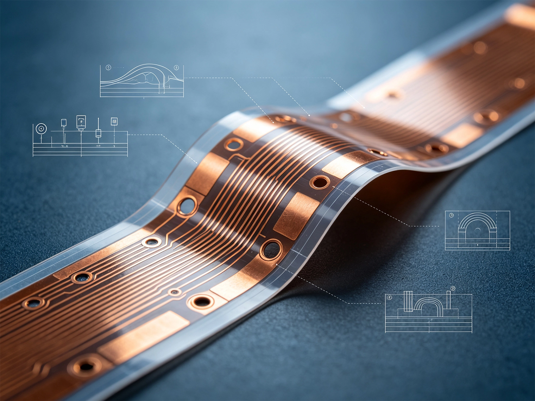
Before diving into prevention strategies, it is essential to understand what causes flexible circuits to fail. Based on industry data and field experience, the primary failure mechanisms include:
Each of these failure modes has specific root causes that can be addressed through proper design practices, material selection, and manufacturing controls.
The Bend Radius is perhaps the most critical parameter in Flexible Circuit Design. When a flex circuit bends beyond its recommended minimum radius, the outer fibers of the copper experience excessive tensile stress, leading to cracking.
The general rule for minimum Bend Radius is:
For Dynamic Flex applications that undergo continuous bending, consider increasing these values by 50% or more for improved longevity.
When routing traces in bend regions, follow these guidelines:
Choosing the right materials significantly impacts Flexible Circuit performance and lifespan. The primary materials include the base film, copper conductor, and Coverlay.
Polyimide (PI) remains the industry standard for flexible circuits due to its excellent thermal stability, mechanical strength, and chemical resistance. However, alternatives exist for specific applications:
The Copper Foil type dramatically affects flex circuit flexibility and fatigue resistance:
For dynamic flex applications, always specify rolled-annealed copper with minimum 50% elongation rating.
Proper trace routing in flexible circuits requires different considerations than rigid board design. The goal is to minimize stress concentration points while maintaining Signal Integrity.
When routing traces in flexible sections:
Stress concentrates at:
Use fillet radii on all trace corners and provide generous spacing around component pads in bend zones.
Strategic use of stiffeners and support structures prevents localized stress while maintaining flexibility where needed.
Apply stiffeners in these situations:
Common stiffener options include:
Coverlay serves as the protective coating for flexible circuits, similar to solder mask on rigid boards. Proper coverlay design protects traces while maintaining flexibility.
For demanding environments, consider these alternatives:
Vias in flexible circuits require special attention because they create stress concentration points during bending.
For applications requiring vias in flex zones:
Successful Flexible Circuit design requires close collaboration with your manufacturer. Design rules vary based on their specific capabilities and processes.
Before finalizing your design, coordinate with your Flex Pcb manufacturer on:
Request a Dfm review early in the design process. Manufacturers can identify potential issues before tooling, saving time and costly revisions.
Prototype testing is essential to validate flexible circuit reliability, especially for dynamic applications.
For critical applications, conduct accelerated testing to predict field performance:
Preventing failures in flexible circuit design requires attention to multiple factors:
By following these guidelines, you can significantly reduce the risk of premature failure in your flexible circuit designs. Remember that each application has unique requirements, and the most successful designs result from close collaboration between designers and manufacturing partners.
The minimum bend radius depends on the flex circuit construction. Single-sided flex typically requires 6-10 times the total thickness, while multi-layer flex may need 15-20 times the thickness. For dynamic applications, use larger radii than minimum specifications.
Yes, but they require specific design considerations including rolled-annealed copper, larger bend radii, and thorough testing. Dynamic flex applications should specify materials rated for high-cycle fatigue.
Copper trace cracking typically results from exceeding the minimum bend radius, using inappropriate copper types, poor trace routing with stress concentration points, or Manufacturing Defects in the Copper Foil structure.
Polyimide offers superior thermal resistance, chemical resistance, and mechanical strength, making it suitable for most applications. PET is more cost-effective but has lower temperature ratings and is only suitable for static or minimal-flex applications.
Stiffeners are recommended around component mounting areas, connector termination points, and anywhere that requires additional support or protection from bending stress. They help prevent failures without significantly impacting overall flexibility in non-stiffened areas.
Flex life depends on design parameters including bend radius, copper type, and application conditions. A well-designed flex circuit can typically endure 100,000 to 1,000,000+ cycles. Specify your cycle requirements to your manufacturer for appropriate material selection.
For more information about flexible circuit design or to discuss your specific application requirements, consult with your Pcb Manufacturing partner.

Detailed Explanation of the Types, Materials, and Applications of Flexible Circuit Boards 101June/04/2026
Metal Core PCB (MCPCB) Basics: Aluminum vs. Copper SubstratesSeptember/29/2026

Sustainability in PCB Fabrication: Eco-Friendly Materials and ProcessesJuly/01/2026
How DFM Analysis Saves You Money on Multilayer PCBsAugust/19/2026
Blind and Buried Vias: Enhancing Density in HDI PCBsSeptember/30/2026

Wearable Health Monitors: The Importance of Biocompatible Flex PCBsSeptember/02/2026
The Hidden Costs of Cheap PCBs: Why Quality MattersJuly/23/2026
What is Rigid-Flex PCB? Complete Guide from China ManufacturerMay/18/2026