
When ordering flexible PCBs, getting the Bend Radius specification right can mean the difference between a reliable product and one that fails prematurely in the field. Yet many engineers struggle with this critical parameter, leading to costly redesigns and production delays. Understanding how to properly specify Bend Radius is essential for ensuring your Flex Circuits perform as intended throughout their operational lifetime.
Whether your designing a wearable device, medical implant, or aerospace application, the bend radius directly impacts Signal Integrity, mechanical reliability, and overall system performance. This guide will walk you through the fundamental principles, industry standards, and practical considerations for specifying bend radius on your Flexible Pcb orders.
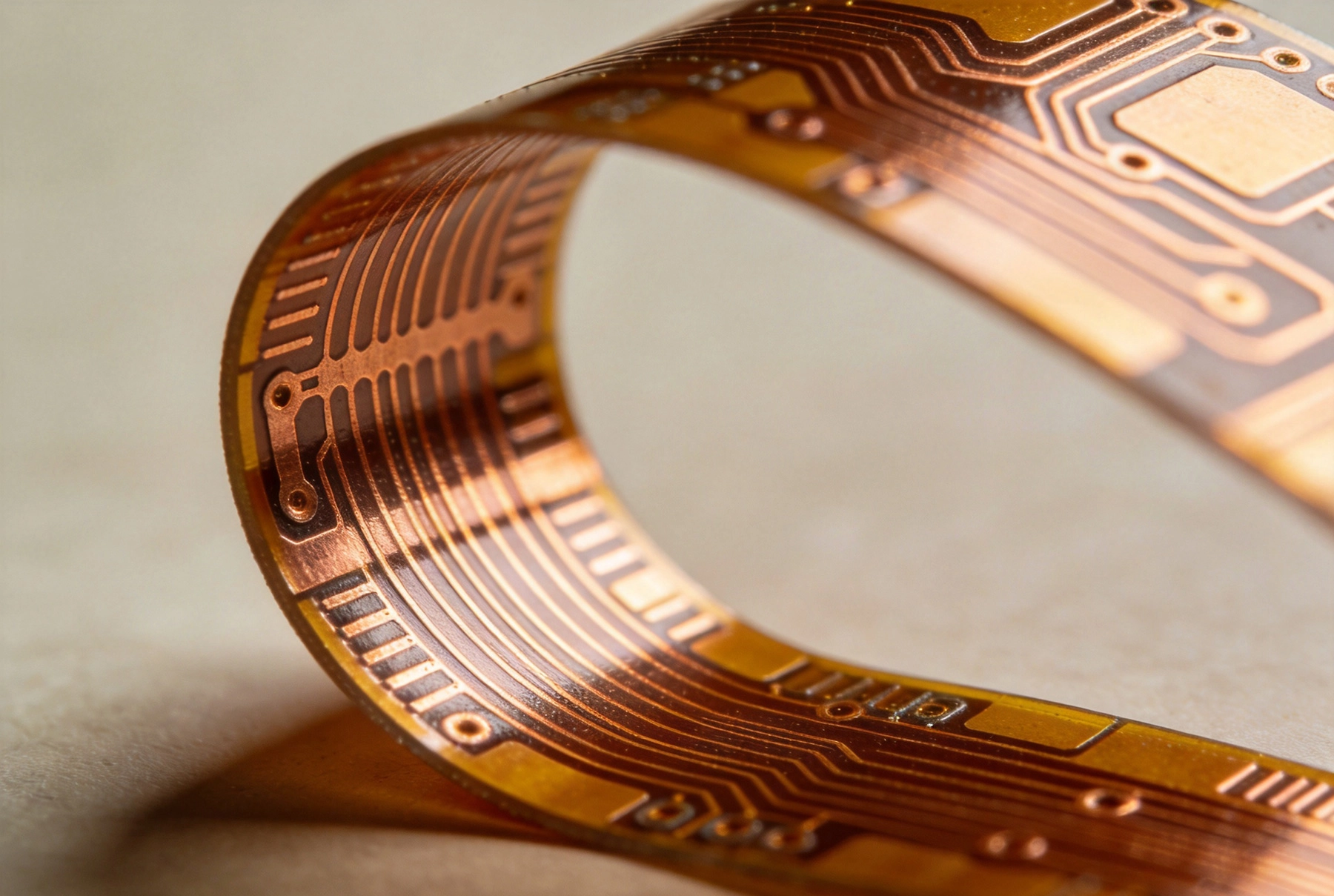
The bend radius refers to the minimum radius at which a Flexible Pcb can be bent without causing damage to the conductors, substrate, or overall circuit integrity. Think of it as the "safest" curve your flex circuit can handle repeatedly without degradation. Specifying this parameter incorrectly is one of the most common reasons for Flexible Circuit failures.
From a physical perspective, when a Flex Pcb bends, the outer surface experiences tension while the inner surface experiences compression. The copper traces on the tension side elongate, while those on the compression side compress. If the bend radius is too tight, this mechanical stress exceeds the materials yield strength, causing permanent deformation or complete failure. The phenomenon is particularly critical in Dynamic Flex applications where the circuit undergoes repeated bending cycles.
The relationship between bend radius and circuit reliability follows a simple principle: larger bend radius equal longer operational life. However, product designers often push for tighter bends to save space, creating tension between form factor requirements and mechanical reliability. Understanding this tradeoff is crucial for making informed design decisions.
Several critical factors determine the appropriate bend radius for your flexible Pcb Design. Ignoring any of these parameters can lead to specification errors and potential field failures.
The total thickness of your Flex Pcb significantly impacts its bending capability. Thicker constructions require larger bend radius because they experience greater mechanical stress during bending. A single-layer flex with 0.025mm Polyimide Substrate will handle tighter bends than a four-layer construction with the same materials.
The stackup construction also plays a vital role. Copper layers placed at the neutral axis (the theoretical plane where bending stress equals zero) experience minimal mechanical stress during flexing. Designers should consider layer placement carefully, particularly in multi-layer flex designs, to optimize for the intended bend radius.
Heavier copper weights increase the overall stiffness of flexible circuits. A design using 2oz copper requires a larger bend radius than one using 0.5oz copper for the same flexing application. The copper type also matters: rolled annealed copper, with its grain structure aligned in the bending direction, offers superior flexing performance compared to electrodeposited copper.
Trace routing within the bend area is equally important. Traces oriented perpendicular to the bend line handle flexing better than those running parallel to the bend. Wide traces distribute stress more effectively than narrow ones, and staggered trace routing in multi-layer designs prevents stress concentration points.
The intended use case dramatically affects bend radius requirements. Static Flex applications, where the circuit is bent once during installation and remains in that position, can tolerate tighter bends. Dynamic Flex applications, involving repeated bending cycles throughout the products lifetime, demand more conservative specifications to ensure reliability.
For static installations, the bend radius can often approach the minimum recommended values. However, dynamic flex applications should specify bend radius at least 10 times greater than the minimum theoretical values to account for fatigue over thousands of bending cycles. This distinction is critical and often overlooked in flexible PCB specifications.
The IPC-2223 standard provides comprehensive guidelines for Flexible Circuit Design, including bend radius specifications. This industry-accepted standard forms the basis for most Flexible Pcb Manufacturing specifications and should be referenced in your design documentation.
According to IPC-2223, the minimum bend radius should be expressed as a ratio relative to the total circuit thickness. For single-sided Flex Circuits, the minimum recommended bend ratio is 6:1 (six times the thickness). Double-sided flex designs should specify a minimum ratio of 10:1, while multi-layer flex circuits require ratios of 12:1 or greater.
These ratios assume standard polyimide substrates with rolled annealed copper. Different material combinations may require adjustments to these baseline values. For applications requiring tighter bends than standard recommendations, design reviews with your flexible PCB manufacturer are essential to evaluate feasibility and reliability tradeoffs.
Calculating the appropriate bend radius for your flexible PCB involves straightforward mathmatics but requires careful consideration of multiple parameters. The basic formula multiplies your circuit thickness by the appropriate ratio from IPC-2223 standards.
For example, consider a double-sided flex PCB with total thickness of 0.15mm (including Coverlay). Using the IPC-2223 recommended ratio of 10:1 for double-sided construction, the minimum bend radius calculation would be: 0.15mm x 10 = 1.5mm. For dynamic flex applications, youd want to specify at least 15mm (10x the minimum) to ensure long-term reliability.
However, calculations must account for real-world factors beyond theoretical minimums. Consider the installation process: if operators must flex the circuit multiple times during assembly, this effectively becomes a dynamic flex application. Environmental factors like temperature extremes and chemical exposure can also affect material properties and should influence your specifications.
Lets work through a complete specification for a wearable medical device. The flex circuit will connect a sensor module to a main board, bending during normal user movement. The circuit has four layers with total thickness of 0.20mm.
Following IPC-2223, the minimum bend ratio for multi-layer flex is 12:1. Minimum bend radius = 0.20mm x 12 = 2.4mm. However, this application involves dynamic flexing (thousands of bending cycles over the devices lifetime). Therefore, we specify 24mm (10x the minimum) to ensure reliable operation throughout the products expected life.
This conservative approach accounts for real-world variables: potential variations in material properties, manufacturing tolerances, and accumulated stress from repeated bending. While the larger radius may require additional space in the product enclosure, the reliability benefits far outweigh the size increase.
Understanding common specification errors helps you avoid costly mistakes. These issues frequently occur in flexible Pcb Design projects and can lead to production delays or field failures.
The most common mistake is specifying minimum bend radius values for applications that involve repeated flexing. Engineers often focus on theoretical capabilities without considering cumulative fatigue effects. A flex circuit that survives initial testing may fail after hundreds or thousands of bending cycles in actual use.
Always evaluate whether your application involves static installation (one-time bend) or dynamic operation (repeated bending). For dynamic applications, multiply minimum values by at least 10x to ensure adequate operational lifetime. This margin accounts for material variations, manufacturing tolerances, and accumulated stress effects.
Copper type significantly impacts flexible Pcb Reliability, yet many specifications omit this critical detail. Electrodeposited copper, commonly used in rigid PCBs, has a columnar grain structure that performs poorly under repeated bending. Rolled annealed copper, with its aligned grain structure, offers dramatically better flexing performance.
For applications involving any bending, specify rolled annealed copper explicitly in your documentation. This selection may add slightly to material cost but provides substantial reliability improvements, particularly in dynamic flex applications.
The bend radius specification alone is insufficient; designers must also consider what happens in the bend area itself. Placing components, vias, or stiffeners within the bend region creates stress concentration points that can lead to premature failure. These features should be located outside the bend zone with adequate clearance.
Trace routing in bend areas requires careful planning. Traces should run perpendicular to the bend direction whenever possible, with gradual transitions rather than sharp corners. Many failures occur because designers treat flexible circuits like rigid boards, routing traces without regard to mechanical stress distribution.
Clear communication with your flexible PCB manufacturer ensures accurate interpretation of your bend radius requirements. Ambiguous specifications can lead to Manufacturing Errors or unnecessary design iterations.
Your design documentation should specify the following parameters explicitly: minimum bend radius value (in millimeters), bend radius ratio (thickness multiple), flex type classification (static or dynamic), and expected bending cycles for dynamic applications. Additionally, specify copper type (rolled annealed recommended), material construction details, and any relevant Ipc Standards.
Include mechanical drawings showing bend locations with dimensions. Cross-sectional diagrams help manufacturers understand layer construction and identify potential concerns before production begins. The more complete your documentation, the smoother the Manufacturing Process.
Request design review meetings with your flexible PCB manufacturer before finalizing specifications. Experienced manufacturers can identify potential issues and suggest optimizations that improve reliability while reducing cost. This collaboration is particularly valuable for applications requiring tighter bends than standard recommendations.
Manufacturers can also advise on material alternatives that may allow tighter bends while maintaining reliability. Advanced materials like liquid crystal polymer (LCP) or specialized polyimide formulations may offer improved flexing characteristics compared to standard substrates. These options are worth exploring for challenging design requirements.
Specifying bend radius for flexible PCB orders requires careful consideration of material properties, application requirements, and industry standards. By understanding the fundamental principles outlined in IPC-2223, calculating appropriate values for your specific design, and avoiding common specification mistakes, you can ensure your flex circuits deliver reliable performance throughout their intended lifetime.
Remember to differentiate between static and dynamic flex applications, specify rolled annealed copper for any bending applications, and collaborate closely with your flexible PCB manufacturer during the design phase. Taking time to specify bend radius correctly upfront prevents costly failures and redesigns in production.
Ready to specify your next flexible PCB project? Our engineering team specializes in flex and rigid-flex circuit design, manufacturing, and assembly. Contact us today to discuss your bend radius requirements and optimize your design for reliability and performance.
According to IPC-2223 standards, minimum bend radius ratios are 6:1 for single-sided flex, 10:1 for double-sided flex, and 12:1 for multi-layer flex circuits. These ratios multiply by your total circuit thickness to determine the minimum bend radius value. For dynamic flex applications, specify values at least 10 times greater than these minimums.
Static Flex applications involve bending the circuit once during installation, with the circuit remaining in position thereafter. Dynamic flex applications include repeated bending cycles during normal operation. If users will bend the circuit multiple times, or if the product involves moving parts that flex the circuit during use, treat it as a dynamic flex application.
Copper type affects mechanical performance under bending. Electrodeposited copper has a columnar grain structure that can crack under repeated bending stress. Rolled annealed copper features aligned grain structure that flexes more naturally, providing significantly better reliability in applications involving any bending. Always specify rolled annealed copper for flex circuits.
Components should never be placed in areas that will undergo bending. Bending creates mechanical stress that can damage component solder joints and cause failures. Design your flex circuit with components located away from bend zones, with adequate clearance to account for material stretch during bending.
Specifying bend radius below recommended values can cause conductor cracking, delamination, or complete circuit failure. In dynamic applications, underspecified bend radius leads to accelerated fatigue and premature failure. Always err toward more conservative specifications, particularly for products with long operational lifetime requirements.

Supply Chain Resilience: Why Diversifying with a China PCB Partner HelpsSeptember/04/2026
ISO and UL Certifications: What They Mean for Your PCB QualitySeptember/23/2026

Sourcing Metal Core PCBs for Automotive LED HeadlightsJuly/25/2026

How HDI PCBs Enable Slimmer Smartphones and TabletsJune/26/2026

How to Verify the Quality of a PCB Prototype Before Mass ProductionOctober/13/2026
ISO and UL Certifications: What They Mean for Your PCB QualitySeptember/26/2026

What to Look for in a Reliable SMT PCB Assembly Partner in ChinaAugust/10/2026

How We Ensure Quality Control in Multilayer PCB LaminationAugust/08/2026