
When engineers design compact electronic devices, they face a critical decision: should they route signals using traditional wire cables and connectors, or invest in rigid-flex printed circuit boards that integrate布线 into a single structure? This choice affects everything from manufacturing costs to product reliability. This article breaks down the true cost-benefit picture so you can make an informed decision for your next project.
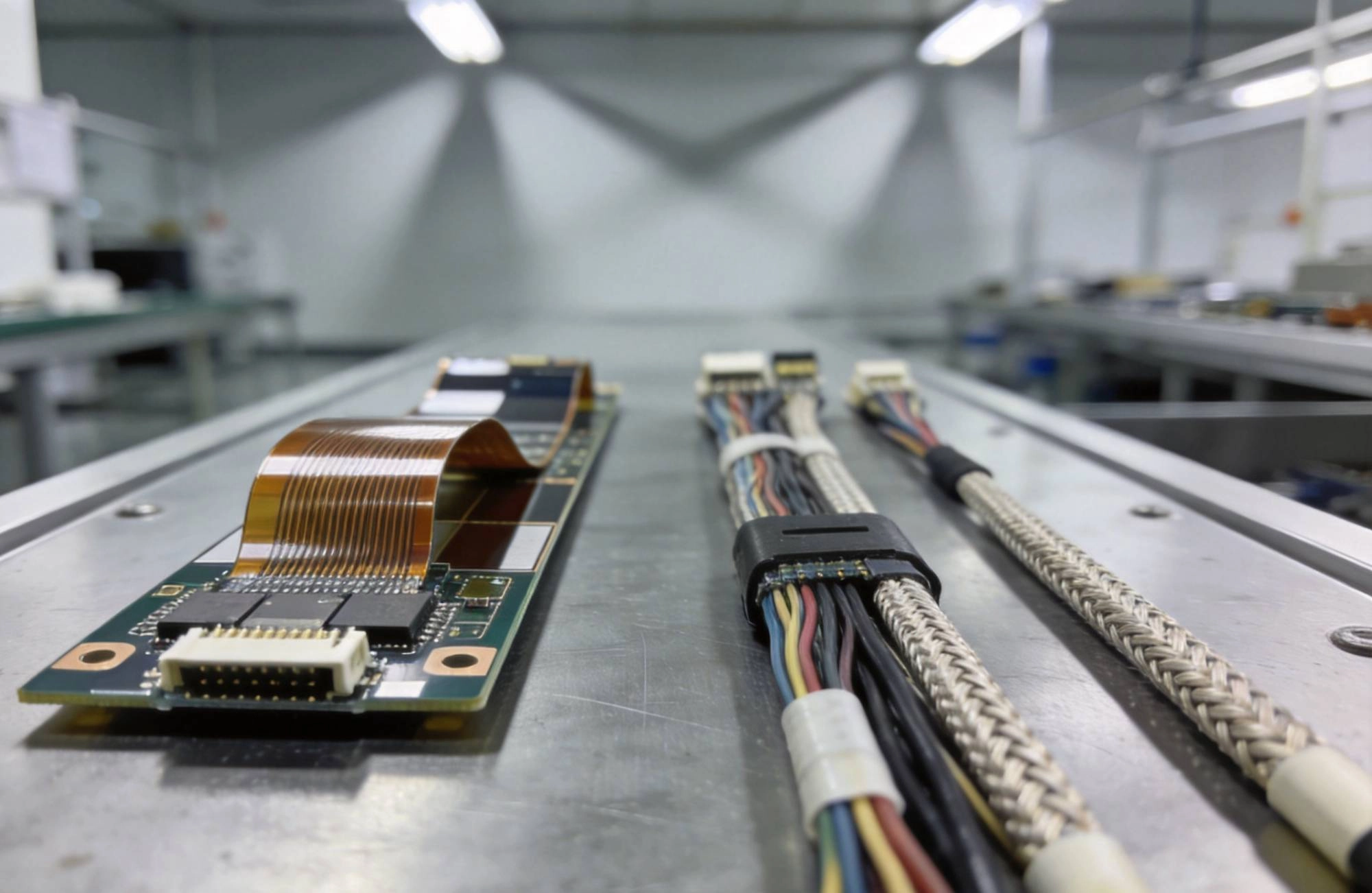
A Rigid-flex Pcb combines rigid board sections with flexible polyimide layers that bend and fold. The rigid portions host components and provide mechanical support, while the flexible sections replace cables and connectors, allowing the board to fit into irregular enclosures or dynamic environments.
Traditional cable assemblies, by contrast, use discrete wires, ribbon cables, or harnesses terminated with connectors. Each signal path requires a separate physical wire, and each connection point needs a mating connector pair.
Rigid-flex boards carry a higher initial price tag. The materials alone—polyimide films, adhesive systems, and Copper Foil designed for dynamic flexing—are more expensive than standard FR-4 and wire. The Manufacturing Process is also more complex, involving multiple lamination steps, careful flex-fold planning, and tighter dimensional controls. A typical rigid-flex board costs two to five times more per square centimeter than an equivalent rigid multilayer design.
Cable assemblies appear cheaper at first glance. Standard wires, crimp terminals, and off-the-shelf connectors are inexpensive. Connectors and wiring can be assembled using relatively simple equipment, even manually in lower-wage regions. Setup costs are low, and design changes to cable routing are generally easy to implement.
However, upfront cost is only part of the equation. When you factor in connector costs, assembly labor, testing, and potential field failures, the gap narrows significantly—or even reverses—in many applications.
One of the biggest advantages of rigid-flex PCBs is the elimination of connectors. Each connector in a cable assembly is a potential failure point and adds material and labor cost. A typical board-to-board connector costs between $0.10 and $2.00 per contact, and a 40-pin connector can easily run $3–$8 in component cost alone. Add mating connectors on both ends, and the connector expense multiplies quickly.
Rigid-flex eliminates most of these connectors. Signals route directly through the flexible layers from one rigid section to another. Assembly simplifies because there is only one "board" to place, not a tangle of cables to route, secure, and terminate. In high-volume production, this reduction in parts count translates directly into lower labor costs and faster assembly times.
Cable assemblies also require dedicated routing and strain relief. Technicians must follow build sheets to route each wire correctly, install cable ties or clips, and apply potting or tape for strain relief. This manual work does not scale as efficiently as automated Pcb Assembly. In contrast, rigid-flex boards go through standard SMT lines like any other PCB, with flex sections handled using carrier fixtures or specialized workmanship.
Rigid-flex PCBs consistently outperform cable assemblies in space-constrained designs. A Flexible Circuit layer typically has a thickness of 0.1–0.3 mm. Compare that to a bundle of discrete wires with insulation, which can easily occupy 3–10 mm or more depending on the number of conductors. In smartphones, wearables, medical probes, and aerospace modules, that thickness difference determines whether the product fits the industrial design or requires a larger enclosure.
Weight follows the same trend. Eliminating individual wires, connector housings, and cable management hardware reduces mass. For portable and airborne devices, every gram matters. A rigid-flex solution can reduce interconnect weight by 40–60% compared to an equivalent cable harness.
The layout freedom that flex sections provide also matters. Flex layers can fold into three-dimensional shapes, routing signals around other components without the minimum Bend Radius constraints that govern cable bundles. This means designers can use the full interior volume of an enclosure rather than dedicating space to cable channels.
Connectors are the weakest link in most cable assemblies. Each mating cycle causes wear on contact surfaces. Vibration and thermal cycling gradually loosen strain-relief connections. Over time, intermittent open circuits or increased contact resistance can develop. In harsh environments—automotive under-hood applications, industrial equipment, or outdoor installations—cable assemblies face additional challenges from moisture, chemical exposure, and mechanical stress.
Rigid-flex PCBs eliminate most of these failure modes. There are no connectors to degrade between board sections. The flex layers are laminated structures with consistent copper bonding, designed to withstand thousands of bending cycles when properly specified. This makes rigid-flex particularly suitable for applications with dynamic flexing requirements, such as foldable displays, printer heads, or robotic joints.
Reliability data from the electronics industry suggests that cable-related failures account for 15–25% of field returns in consumer electronics and a higher percentage in industrial equipment. Reducing the connector count directly reduces this failure category.
Rigid-flex allows designers to integrate functions that would otherwise require multiple boards and cable connections. Power and ground planes can extend through flexible sections, providing stable distribution across the assembly. Controlled Impedance traces maintain Signal Integrity through the flex region when designed with appropriate stack-up and Coverlay. Shielding layers can be incorporated into the flex layers for EMI-sensitive applications.
Cable assemblies offer flexibility in a different sense—they are easier to modify during prototyping. If a design change requires rerouting a signal, swapping a cable is straightforward. Rigid-flex board modifications typically require retooling the fabrication, which adds time and cost. This makes cable assemblies more attractive for early-stage products where the design is not yet stable.
Rigid-flex PCBs integrate with standard ICT (in-circuit test) and flying probe systems. Test points can be placed on both rigid and flex sections, and automated test coverage is typically high. The continuity of traces through flex sections means fewer test access points are needed overall.
Cable assemblies require different testing approaches. Each conductor must be verified for continuity and correct termination. In high-pin-count harnesses, this testing can be time-consuming. Reverse termination errors—where wires are swapped at one end—are a common defect that testing must catch. Automated cable testers exist, but they add equipment cost and cycle time.
To illustrate the true cost picture, consider a mid-volume industrial control module with 12 board-to-board connections. A cable assembly approach might use 12 matching connector pairs at $1.50 each, plus cable materials and assembly labor. Total component cost per unit could reach $35–$50 for interconnect alone.
A rigid-flex alternative consolidates those 12 connections into traces running through the flex section. The rigid-flex board costs more to fabricate—perhaps $25–$40 premium over a standard multilayer—but eliminates $35–$50 in connectors and reduces assembly time by an estimated 15–20 minutes per unit at typical labor rates. The net cost difference becomes neutral or even favorable for rigid-flex, while adding reliability and reducing assembly complexity.
At higher volumes, the economics favor rigid-flex even more strongly. Unit costs drop as fabrication yields improve and setup costs are amortized. Cable assembly costs do not benefit from the same economies of scale because connector and wire costs remain relatively fixed.
Rigid-flex is not always the right choice. Cable assemblies make sense when the design is still evolving, when very high current or voltage exceeds the capacity of PCB traces, when field serviceability requires easy connector replacement, or when the production volume is so low that the rigid-flex tooling cost cannot be justified.
Some applications also require connectors for modularity—allowing subassemblies to be separated and reconnected in the field. In these cases, cable assemblies with connectors provide serviceability that rigid-flex cannot match without adding complexity.
The decision framework is straightforward. Calculate the total interconnect cost for the cable assembly approach: connectors, wires, labor, testing, and an estimate of expected field failure rate. Compare that against the rigid-flex fabrication and assembly cost, factoring in improved reliability and reduced failure-related costs.
For most compact, mid-to-high-volume products, rigid-flex PCBs deliver better Total Cost Of Ownership despite higher upfront fabrication costs. The savings come from fewer parts, simpler assembly, reduced failure rates, and better use of enclosure space. Designers who have made the switch rarely go back to cable assemblies for space-critical applications.
The right choice depends on your specific volume, design stability, and reliability requirements. But for projects where size, weight, and long-term reliability matter, rigid-flex deserves serious consideration in every cost-benefit analysis.
Tags: Rigid-flex Pcb, cable assembly, cost analysis, Pcb Design, Electronics Manufacturing, interconnect solutions, PCB vs cable, Design For Manufacturing
Total Cost Of Ownership to make the right interconnect choice for your electronics project." />
The Complete Step-by-Step Process ExplainedJune/05/2026
Thru-Hole vs. SMT: Choosing the Right Assembly Technology for Your PCBJuly/10/2026

Understanding PCB Assembly Prices in China: What Factors Influence Cost?June/10/2026
What is a Multilayer PCB? A Comprehensive Guide for EngineersJuly/02/2026
PCB Assembly Price China: A Complete Cost Guide for 2024May/18/2026
How to Reduce Your PCB Manufacturing Costs Without Sacrificing QualityJuly/08/2026
How Automated Optical Inspection (AOI) Ensures SMT QualityAugust/15/2026

The Future of PCB Manufacturing in China: Trends for 2026 and BeyondMay/19/2026